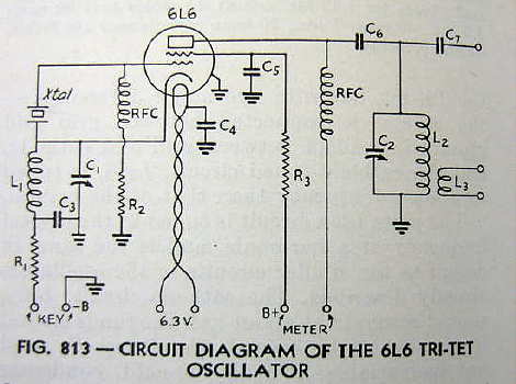
In June 1933, QST's Technical Editor, James Lamb (W1CEI), published an article describing a revolutionary new type of crystal oscillator -- one that would dominate most amateur transmitter designs for the remainder of the decade and the outbreak of World War II. Lamb's article described the unique use of a single tetrode or pentode working as both a crystal oscillator and as a harmonic-generating amplifier. The circuit was harmonic-rich as well as stable. Tuning the output plate tank had little effect on the crystal's frequency or its ability to sustain oscillation. The oscillator was similar to a normal triode grid-plate oscillator but used the screen as the 'plate'. The tuned circuit normally seen in the plate circuit was placed in the cathode end of the electron stream, allowing the screen to be grounded for RF. The normal cathode-plate circuit was used as a hard-driven harmonic-generating screen-grid amplifier tuned to the crystal's desired harmonic. Such an arrangement could allow amateurs to use just one crystal on two bands and eliminate the need for a second stage to get to the next higher band. In 1933 most hams could ill-afford many crystals as a typical 40m crystal was priced at $20, a costly investment in the hungry 30's.
Lamb called his circuit a 'Tri-tet' oscillator because of its triode oscillator and tetrode amplification properties. Interestingly, Lamb's circuit may have been partialy inspired by an earlier and somewhat similar one in principle. David Newkirk's treatise, 'Trials and Tribulations of the Tri-Tet Oscillator', describes a short article by William Durkin, W2DHM, appearing in December 1932 QST's 'For The Experimenter' column . Durkin's circuit also described the use of either a tetrode or pentode as a crystal oscillating 'doubler'. Unlike Lamb's circuit, the crystal oscillating tank was placed in the screen circuit rather than in the cathode, allowing the desired harmonic to be tuned in the tube's plate circuit, the same as Lamb's....an eerily similar circuit that seems to have gone largely unnoticed.... or perhaps not!
Certainly a 'Tri-tet' oscillator by any standard defintion, Durkin even describes using an 80m crystal to obtain 5 watts of output on 40m, something entirely unique at the time. Lamb's article went on to describe a low-powered circuit that could be used to feed successive stages of amplification but stopped short of describing its outright use as a stand-alone two-band transmitter. Transmitter projects published in QST soon started to utilize the Tri-tet crystal oscillator and multi-band two stage transmitters quickly became a reality. Development of a practical single-tube Tri-tet transmitter was left to QST's Assistant Technical Editor, George Grammer (W1DF), who less than a year later, described just such a project in "A One-Tube Crystal-Controlled Transmitter" in QST of March, 1934. Grammer's transmitter presented an easily duplicated breadboard-style transmitter that worked well on two bands with just one crystal...either on 160 and 80m, with a 160m crystal or on 80 and 40m, with an 80m crystal. Subsequent designs would later describe operation on 20m as well, using a 40m crystal. Although Lamb's original article describes measuring useful 'harmonic power' on the third and fourth harmonics (tripling and quadrupling), it seems this application was only put into practice when used in multi-staged transmitters and rarely, if ever, in single-tube, stand-alone transmitter designs. Although it is very likely that more than a few Novices from the 50's tried tripling their one-tube Tri-tets to 15m, I have not read or heard of anyone using a Tri-tet up on 10m.
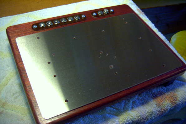
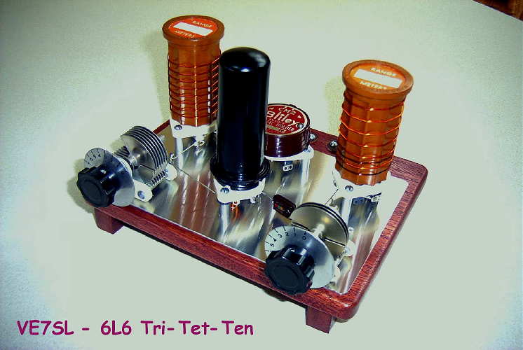
Over the years I had often pondered how unique a single-tube Tri-tet transmitter quadrupling to 10m from a 40m crystal might be. Would there be any useful power available from the fourth harmonic? Would the transmitter key well enough to actually be used on the air? What tube would be best? Earlier this winter I was able to begin my attempt to answer these questions. Mid 30's construction practices saw a steady transistion from breadboard-based building to aluminum chassis construction and many of the most unique and attractive looking projects combined the best features of both. Components were often mounted directly upon or raised above a polished aluminum ground plate which itself was mounted to an attractive breadboard base.
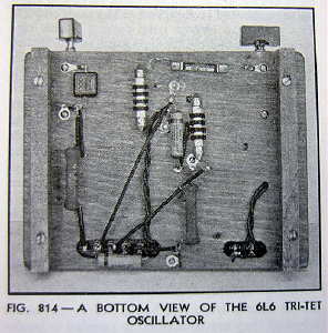
The Tri-tet transmitter (160/80/40/20m) described in the 1938 Radio Amateur's Handbook (A Practical Crystal-Oscillator Transmitter) gave me the opportunity to not only try building a unique 'high-frequency' Tri-tet but also to utilize this attractive but short-lived construction style. With the peak of Solar Cycle 24 fast-arriving, the opportunity was difficult to resist!
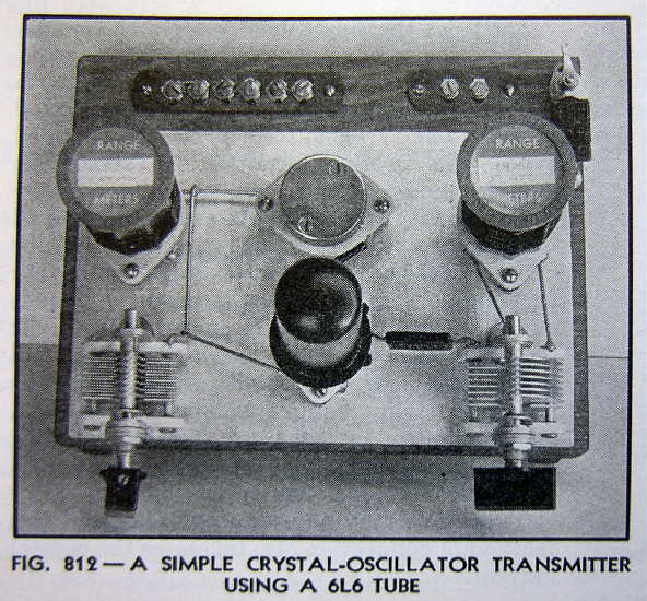
EARLY TESTSTesting began by building a series of test-bed models using the 6L6 as well as trying the RK-39 (early 807 type), the 807, and the 6AG7. In all cases, only the 10m fourth harmonic was observed. As well as building the 'Handbook' version shown below, the resonated screen-tank circuit version was also built. My original goal was set at generating at least 1 watt of spectrally-clean RF on 10m as well as something that keyed 'acceptably'. I reasoned that 1 watt of RF would be enough to work many stations on 10m during periods of good propagation. As well, I knew that no matter what version I used, the signal would be chirpy on 10m ....but would it be too chirpy to actually put on the air?
Over the years, the Tri-tet seems to have developed the unfair reputation of being a 'crystal-cracker'. Most (if not all) cases of crystal damage were likely due to improper keydown tuning of the cathode tank circuit. The cathode tank circuit should never be tuned to the actual crystal fundamental frequency and especially when trying to operate the transmitter on the crystal's fundamental frequency. When operating on the fundamental, the normal procedure was to short or switch out the cathode tank circuit altogether, while when operating on crystal harmonics, the tank was to be resonated somewhat higher than the crystal frequency.
Over the next several weeks of building and testing, the best performing tube, in terms of output and keying, was the 6L6. All of the other tubes produced either lower outputs (approximately 1 watt) or poorer keying characteristics even when grid leak values and screen voltages were fine-tuned. The RK-39 and the 807 were particularly touchy when tuning the cathode tank, as various tuning combinations would quickly lead to loss of oscillation unless tuning was precise. Output power often initially looked promising until filtered for only 10m RF, indicating the high harmonic content available in the output. Tuning on all of the test models required the use of a calibrated wavemeter (RF-sniffer), along with a 50 ohm resistive load at 10m. Cathode tuning was found to be particularly critical until fully understood. My cathode tank circuit values were selected so that it would be impossible to tune through the crystal's fundamental frequency on 40m and resonated from 10MHz to 18MHz. The best keying characteristics for 10m operation of the finished version were found to occur when the cathode tank was tuned to 14 MHz. It also coincided with the point of lowest unwanted harmonic content appearing in the output. Tuning through this point produces a very nice noticeable 'peak' in both 10m output and plate current, with both values dropping off either side of the 14 MHz point. Tuning the tank lower in frequency towards 10 MHz produces another rise in plate current and output but most of the output is not 10m energy and the keying characteristics degrade noticeably.
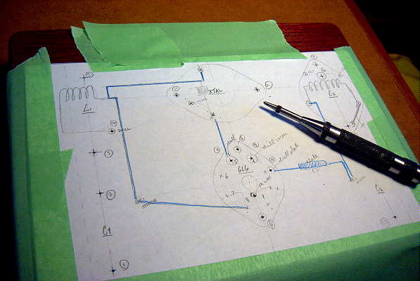
BUILDINGOnce I had decided on the final circuit to construct, a full-sized parts-placement plan was drawn up and taped to the aluminum groundplane.
Once both the sheet and breadboard were drilled, parts were mounted, trying to keep as close to the original plan as possible.
During the soldering phase, the entire aluminum plate was masked-off in order to prevent any scratches from occuring.
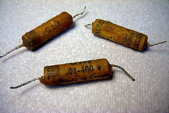
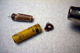
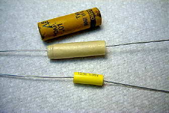
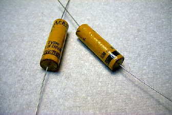
In keeping with the correct period, some very old paper capacitors were re-packed with modern ones of the proper value.
A heat gun was used to remove the old interiors and the new ones resealed with wax poured into the ends.
The final circuit values were optimized for best keying and maximum 10m output.
Additionaly, one part not appearing in the original plan was added, which almost doubled the 10m output power, that being the bypass capacitor (C7) on the plate RFC feedline.
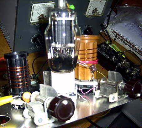
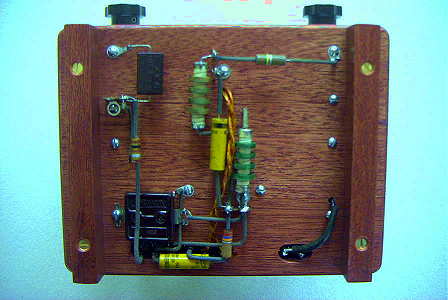
The completed transmitter turned out very close in appearance to the original '38 Handbook version.
Thanks to the pre-built shakedown model, the transmitter fired-up with no problems.
ON THE AIR!The final version turned out to perform better than the test-bed version, likely because of better circuit grounding, shorter leads, lack of numerous clip leads coupling into each other and a more efficient L2/L3 output tank. I am able to obtain almost 4.5 watts of spectrally clean 10m RF, far exceeding my original hopes. The keying is chirpy but acceptable and far better than I had hoped, considering all keying anomalies are multiplied four times by the time they reach 28MHz. Both regulated screen voltage as well as a voltage divided screen source were tried but with no apparent difference in keying. The keying can be made to sound Collins-like but at the price of much-reduced power output (approximately 1 watt). Tuning-up on 10m shows a very nice 'dip' in plate current when resonating. The addition of a small variable capacitor in series with the two-turn output link allows the transmitter to be fully loaded, almost pi-network like, into the 50 ohm antenna system. Without this capability, output power is limited to approximately 2 watts.
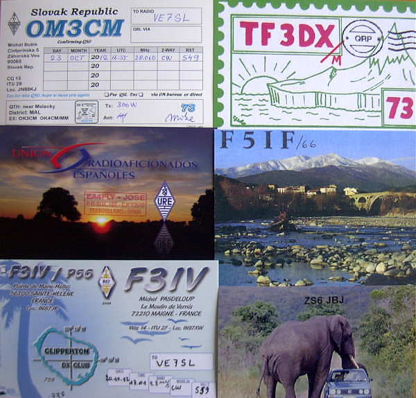
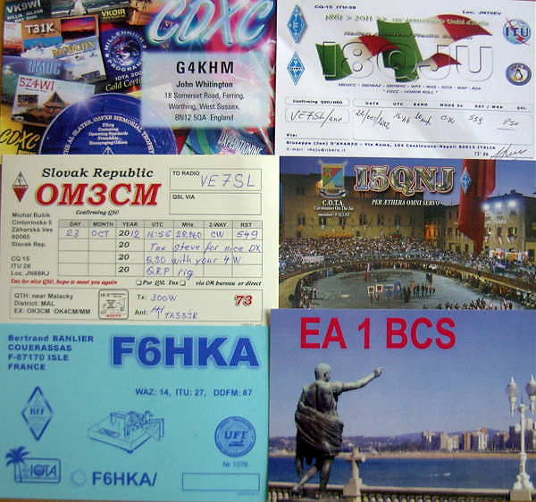
In the few weeks since completing the TRI-TET-TEN, I have had many dozens of good solid QSO's on 10m CW, having worked 15 states and 6 DXCC countries despite the less than stellar conditions. Paul, K8JCC, was kind enough to send an audio file of my signals as heard in Michigan while I was in QSO with W4ABC in Florida, while Bill, AK5X in Texas, posted a nice video of our recent 10m QSO.
- - - - Click here for an ON-AIR RECORDING made by K8JCC in Michigan. - - - -
- - - - Click here to access THE AK5X VIDEO FILE made by AK5X in Texas. - - - - With the arrival of the F2 season, ten meters has picked-up once again. On Oct 5th, my 10m CQ was answered by Paul, G4RRA in S-W England!! My dream of working Europe with the tri-tet came earlier than expected.
- - - - Click here for an ON-AIR RECORDING made by G4RRA in Spreyton, England. - - - -
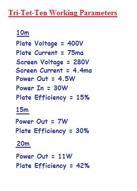
At first glance these efficiency numbers appear rather dismal but most power oscillators, unlike typical Class C amplifier stages, are dreadfully inefficent.
Although low, the values are very similar to Lamb's predicted values for expected 2nd, 3rd and 4th harmonic output powers.
Using the Tri-Tet-Ten is a huge delight and usually evokes an interesting comment regarding the keying. Many operators have told me that they were attracted to the keying and wanted to find out what I was using, as they knew it was 'something different'. Several 'older' ops have commented that the note reminded them of the 'good old days' when there were many unique-sounding signals on the air.I look forward to making many more QSO's on 10m CW during the peak years of Solar Cycle 24 and can normally be found on 28042 kHz, using my original Vibroplex purchased in 1963...please give me a call should you tune across an 'unusual' sounding 'CQ'!
SUCCESS!
With the return of high solar-flux values for a few days in late October (2012), I was able to work several Europeans on my crystal 'CQ' frequency! What a thrill it was to finally achieve my initial goal, of working Europe on 10m with a single-tube, 40m crystal-controlled oscillator!