WARG Takes on International
HF Beacon
An offer was made to the VK6 WIA to install and manage an International
HF Beacon in Perth. The beacons are provided by The Northern
Californian DX Foundation at no cost.
WARG volunteered to install the beacon at its Roleystone site. This
offer was accepted by the VK6 WIA.
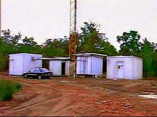
The "photo" on the left is a frame grab from a video camera showing
the 4 buildings at the Roleystone site.
Our's is second from the left. The HF beacon's antenna, a Cushcraft
R5 multi band vertical is 80 metres away in line with the car and our
building. The R5 antenna was tried attached to our building but as expexted
the 100 Watts of RF got into all sorts of equipment, and in particular
the packet system on site.
Although this project is not voice repeaters it is thought that the
international importance of the project more than justified WARG's involvement.
WARG also has the site and the expertise to install and maintain the beacon.
Roleystone site Perth
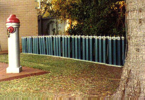 This
photo was found in the WARG album. It shows the results of the cavity building
project in 1981/82. A total of 11 X six cavity
duplexers were built; that is 66 full size two metre cavity
filters. These duplexers are all over the country now, with only 1set held
in reserve for tuning up and swapping with any duplexer that has gone faulty.
The cavities are made out of copper tubing. The outside tubing is 4" and
the inside tuning element 1 3/8". All were soft soldered together after
being turned up on a lath. The silver coloured boxes on the top contain
the in/out connectors and the connections to the coupling loops along with
the notch C & L elements. The design was taken from the ARRL Repeater
Handbook.
This
photo was found in the WARG album. It shows the results of the cavity building
project in 1981/82. A total of 11 X six cavity
duplexers were built; that is 66 full size two metre cavity
filters. These duplexers are all over the country now, with only 1set held
in reserve for tuning up and swapping with any duplexer that has gone faulty.
The cavities are made out of copper tubing. The outside tubing is 4" and
the inside tuning element 1 3/8". All were soft soldered together after
being turned up on a lath. The silver coloured boxes on the top contain
the in/out connectors and the connections to the coupling loops along with
the notch C & L elements. The design was taken from the ARRL Repeater
Handbook.
Cavity Filters all 66 of them
The inside of a two metre cavity filter. Although full size cavity
filters for two metres may seem complex, they are just copper tubing. The
outside tube is 4" in diameter and surrounds the inner 1 3/8" tube. This
tube, which is soldered to the top plate, has to be adjustable length wise.
This is done by sliding the 1" diameter tube up and down inside the 1 3/8"
tube by means of the threaded rod. These two tubes are in electrical contact
by cutting slots in the bottom of the 1 3/8" tube and bending the pieces
in to tightly contact the 1" tube. The length can then be varied to frequency
tune the cavity. RF energy is feed into and out of the cavity by the two
coupling loops. These loops couple to the centre tube. When the centre
tube is 1/4 of a wave length at a given frequency maximum energy is coupled
between the loops.
Page 5
To Page 6