![]()
home
UK Larkspur C42 VHF FM Radio
|
|
|
|
|
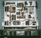
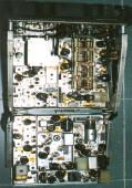
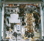
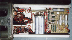
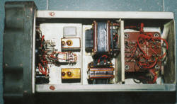
| Inter view of the C42, it employed modular design for easy maintenance. | C42 consists of 2 parts, upper part is IF, AF amp., cooling fan, TX audio, inter audio amp. etc, lower part is the RX and TX RF part. | The lower part of C42, the big 8-gang variable capacitor is on the left side, small metal box on the left is the RX local oscillator VFO. The left side module is the TX RF part. | The upper part of C42, the left side module is the RX IF. Central module is the TX audio , and the right is the TX cooling fan control unit, C42 runs very hot in a sealing cabinet, and cooling fan is required. |
|
|
|
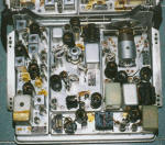
| This is the all solid state power supply for the C42 radio. It replaced the early model which used vibrator type design. Above photo is the lower side of the supply, large filter capacitors located at the central, the right side is the DC rectifier circuit board. | The upper side of the power supply. Right side is the conversion transformer, central is the filter choke, the left side is the control relay, please note it is not vibrators. |
Please click the above photographs for super large size.
This is the UK Larkspur VHF radio. Frequency range is from 36 to 60 MHz.Frequency control is by means of VFO. It is a all tube type design employed all 6.3V e.g. 6AK5. C42 RF power output is 15 Watt maximum. Power supply is 24V DC and require 15A DC. The left hand side as in the photograph is the all solid state power supply.