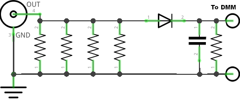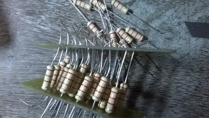
Dummy loads are useful for the experimenter in the ham shack and can be built using a collection of carbon resistors in parallel. All the resistors are to be of the same resistance value and same wattage so that heat dissipation is equally shared among all the resistors. The power handling capacity of the dummy load is the sum of all the individual wattage of the resistors. For example three numbers of 2watt resistors can handle 6watt in total and ten numbers of 2watt resistors can handle 20 watt in total.
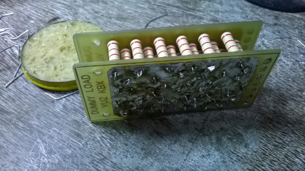
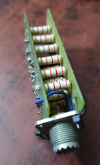
For QRP testing, the number of resistors are less in number and can be directly soldered on to a connector. For more number of resistors (more wattage), a PCB can be used. I used a glass epoxy PCB made by VU2KBX. Any general purpose dotted PCB may also be used. VU2KBX's design used two PCBs in sandwich style to evenly space the resistors and allow air flow in between. For relatively fewer resistors, a single PCB may be used with resistors mounted in the usual way. The lead lengths of resistors are to be kept at a minimum to avoid inductance.


The reciprocal of the effective resistance is equal to the sum of reciprocals of the individual resistors.
1/R=(1/r1)+(1/r2)+(1/r3)...+(1/rn)
To calculate the number of resistors of a particular value, to get 50 Ohm effective resistance, we use the formula
Number of resistors = 1/(50/individual resistor value)
Resistance value depends on the number of resistors. Effective wattage is the sum of wattage of all resistors. (For example, using 2 numbers of 2 watt resistors will give a 4 watt dummy load. Using 10 numbers of 2 watt will give a 20 watt dummy load.) Caveat - All resistors to have identical values and wattage so that heat is dissipated equally among all resistors.
| Calculate the number of resistors required to get 50 ohm, using some standard resistor values | |
Diode: 1N4148 or any small signal diode. For milliWatt operation, Schottky or Germanium diode may be considered (not a necessity though). The maximum reverse bias voltage for 1N4148 is 75V. This should be okay for upto around 100 watt. Please check the datasheet of the diode you are using.
Capacitor: ~ 0.01 mfd with sufficient voltage rating
Resistor: The resistor across the capacitor is for
bleeding off the charge on the capacitor.
| Calculator
for approx DC voltage for given power (Voltage will depend on voltage drop across diode, depending on it's type) |
||
| |
Watt |
|
Compact tables of wattage vs voltage for pasting on the enclosure of the dummy load. Please select the table depending on the type of diode used, and print selected text or paste into a word processor for further embellishments before printing.
| Watt vs Volt across 50 Ohm dummy load Using silicon diode |
|||||
| Watt | Volt | Watt | Volt | Watt | Volt |
| Watt vs Volt across 50 Ohm dummy load Using schottky or germanium diode |
|||||
| Watt | Volt | Watt | Volt | Watt | Volt |