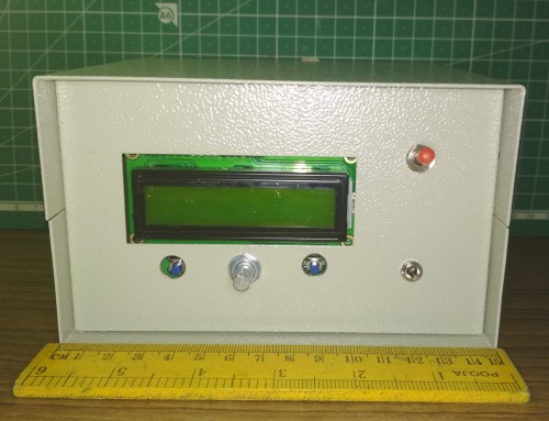
My rig was built by Bangalore Amateur Radio Club (BARC) as part of a group build. It follows the Triband version hardware by WB2CBA, Barb. The firmware is by PE1NNZ, Guido. The project is housed in a metal cabinet. One extra EP socket (un-wired) is provided on the front panel. There are three PCBs, the Main board, LCD board and the PA board. The reference frequency crystal used is 25 MHz.
| Firmware version | 1.02r |
| BAND 1 | 40m |
| BAND 2 | blank |
| BAND 3 | 20m |
You can read about how PE1NNZ, Guido made some modifications to transform the QCX transceiver into an SSB transceiver here in his blog. You can read about QCX-SSB, in the GitHub pages of the project here and also the many forks of the project here. You can read about DL2MAN, Manuel's uSDx Sandwich hardware for Guido's software, in his website here. You can also read about WB2CBA, Barb's version of hardware for Guido's software, here in his blog post. To understand direct SSB generation by frequency modulating a PLL, you can read Guido's blog post here.
There are quite a few versions or ‘builds’ available on the planet and lot of information is also available on the internet. I thought I will jot down the details for my rig, to understand the features that may be specific to this build. My rig belongs to the first batch of the BARC group build for uSDX Tribander.
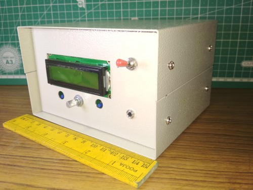

On/Off toggle switch on the top right.
Left button: Enter into menu from main screen
Encoder:
Rotation: Tuning dial | Changes Menu Items and options
Single press: select menu | set menu option
Double press: Change band
Right button: Exit from menu option | Exit from menu to main screen | Quick change of mode LSB/USB/CW when on the main screen (AM and FM can not be quick set here. Please use menu 1.2 for all modes)
EP socket: Unconnected spare. I can wire my own
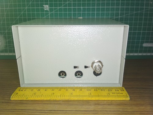
First Row (left to right) - Slide switch SW1, Slide switch SW2, BNC antenna socket
Second Row (left to right) - EP socket for PTT Mic, EP socket for headphones, DC socket (barrel is ground, center is positive)
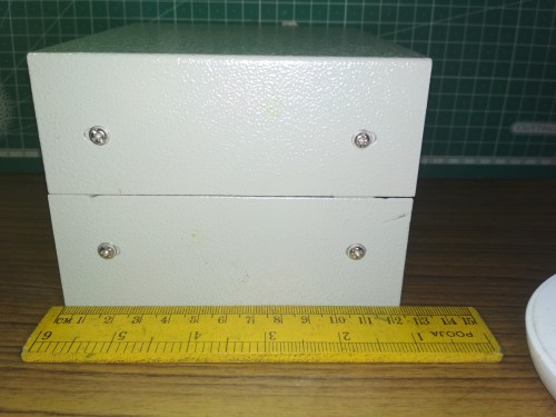
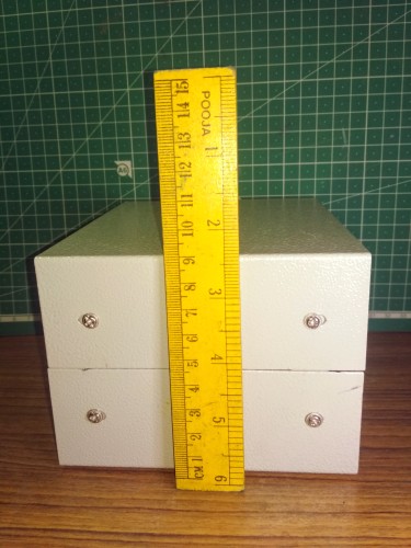
A single press of the left button will open the menu. Each menu is numbered. Rotating the encoder changes the menu. The current option is displayed below the menu name. Pressing the encoder selects the menu. When a menu is selected, the symbol > is displayed before the option. When the encoder is rotated, the '>' symbol becomes '>' and the currently selected option changes to other available values. After selecting the desired option, the encoder can be pressed (or the right button pressed once) to set the option and unselect (exit) that menu. Now the '>' symbol disappears.
Example:
The first menu is the volume.
+-------------------------
| 1.1 Volume
| +10
+--------------------------
In the above example, the Volume menu is displayed. Below the menu name, the current option '+10' (in this example) is displayed.
When the encoder is pressed, the menu is selected. The character '>' is displayed before the current option (as shown below).
+-------------------------
| 1.1 Volume
| >+10
+--------------------------
Now, when the encoder is rotated, the '>' symbol becomes '>' (as shown below) and the options change one by one, as the encoder is rotated.
+-------------------------
| 1.1 Volume
| >+11
+--------------------------
When the desired option is reached, the encoder is pressed (or the right button is pressed once) to set the menu and unselect it. The display will be as shown below:
+-------------------------
| 1.1 Volume
| +11
+--------------------------
At this stage if the encoder is rotated, the next menu will be displayed and so on... If we want to exit the menu and go to main screen, the right button is pressed once. Now, the menu is closed and the main display is shown.
Firmware version: R1.02t
| Menu | Options Available | Remarks |
|---|---|---|
| 1.1 Volume | -1 to +16 in steps of 1 | |
| 1.2 Mode | LSB, USB, CW, FM, AM | |
| 1.3 Filter BW | Full, 3000, 2400, 1800, 500, 200, 100, 50 | BW = Bandwidth |
| 1.4 Band |
160m, 80m, 60m, 40m, 30m, 20m, 17m, 15m, 12m, 10m, 6m |
This is only software selection. Hardware selection to be done
using switches. |
| 1.5 Tune Rate |
10M, 1M, 0.5M, 100K, 10K, 1K, 0.5K, 100, 10, 1 |
|
| 1.6 VFO Mode | A, B | |
| 1.7 RIT | OFF, ON | |
| 1.8 AGC | OFF, Fast, Slow | |
| 1.9 NR | 0 to 8 in steps of 1 | Noise Reduction |
| 1.10 ATT | 0dB, -13dB, -20dB, -33dB, -40dB, -53dB, -60dB, -73dB | Analog Attenuator |
| 1.11 ATT2 | 0 to 16 in steps of 1 | Digital Attenuator |
| 1.12 S-meter | OFF, dBm, S, S-bar, wpm | Type of S-Meter |
| 2.1 CW Decoder | OFF, ON | |
| 2.4 Semi QSK | OFF, ON | |
| 2.5 Keyer Speed | 1 to 60 in steps of 1 | |
| 2.6 Keyer Mode | Iambic A, Iambic B, Straight | |
| 2.7 Keyer Swap | OFF, ON | |
| 2.8 Practice | OFF, ON | Disable Tx for practice puposes |
| 3.1 VOX | OFF, ON | |
| 3.2 Noise Gate | 0 to 255 in steps of 1 | |
| 3.3 TX Drive | I don't want to change now (On my rig 6) | |
| 4.1 CQ Interval | 0 to 60 in steps of 1 (On my rig 5) | Idle time in seconds, before new CW message is given |
| 4.2 CQ Message | CQ PE1NNN + | Default. We can change this. |
| 8.1 PA Bias min | I don't want to change now (On my rig 20) | PA amplitude PWM level for representing 0% RF output |
| 8.2 PA Bias max | I don't want to change now (On my rig 74) | |
| 8.3 Ref freq | I don't want to change now (On my rig 25000720) | |
| 8.4 IQ Phase | I don't want to change now (On my rig 90) | |
| 10.1 Backlight | OFF, ON |
This build of the tribander has two bands built into it, leaving one slot free for the user to choose and build as per his requirement. As it is, I can work the 40m and 20m bands. In this build, bands have to be selected at the software level (using menu selection) as well as the hardware level (using the slide switches on the rear panel. There are two slide switches SW1 and SW2 on the rear panel. Each switch has three positions ie., (L)eft, (Middle) and (R)ight as viewed from on the rear panel.The middle position is not used and free for the user's choice of band.
| Band | SW1 | SW2 |
| BAND 1 (40m) | L | L |
| BAND 2 (User) | M | M |
| BAND 3 (20m) | R | R |
I use a pair of Philips 'over the ear' headphones for comfortable listening. If you wish to use the built-in speaker of the supplied PTT-Mic, you can use a stereo cable to plug into the socket provided in the mic and plug the other end of the cable into the headphone socket in the rear panel of the rig. The volume is very low as the output is designed for headphones, but may be usable in some situations when held closer to ear. After trying it for some time, I recommend the use of headphones.
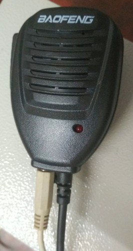
The ptt-mic socket doubles as the morse-key socket. Morse key can be plugged into the mic socket at the rear. The menu 2.6 (Keyer Mode) to be set according to the key you are using. When you are using paddles, either 'Iambic A' or 'Iambic B' option can be chosen according to your preference. When you are using a straight key or cootie key or bug key, the 'Straight' option to be selected. When using a straight key, if the rig is not toggling to Tx when the key is pressed down, the menu 2.7 (Keyer Swap) may need to be set to 'ON' option. Similarly when using paddles, if the 'dits' and 'dahs' are reversed, the menu 2.7 (Keyer Swap) may need to be set to 'ON' option. When you are using an external keyer with your paddles or when you are using a touch paddles cum keyer (like the ones made by VU2RWH, Ram) you have to set the menu 2.6 (Keyer Mode) to 'Straight' option.
When working CW, you may want to have the decoder on. If you wish to do so, the menu 2.1 (CW Decoder) to be set to 'ON' option, The decoded text will scroll on the first line of the display. If you feel that the signal is not strong enough for decoding, you may want to check menu 1.8 (AGC) and try the 'OFF' option.
The rig can be used as a code practice oscillator. An added advantage is that you can see your code on the decoder to verify and correct your sending. To setup the rig as CPO, the menu 2.8 (Practice) to be set to 'ON' option. When the rig is set up for practice, transmit is disabled. So when you want to transmit, remember to set this option to 'OFF'.
The rig performs well for its intended use. I have made a few QSOs with it, contacting local Chennai stations and also stations in neighbouring state Kerala. After enjoying your rig for sometime as it is, you may get ideas for enhancing your experience. Some ideas may be implemented without even opening the covers while some other ideas may entail opening the covers and more.
The rig did not come with a knob for the encoder. It is possible to easily tune using only the shaft of the encoder, as the tuning rate is adjustable via menu 1.5 as well as by pressing the encoder shaft. You may want to add a knob for the encoder not only to make it a bit more easier to use but also to enhance the look of the rig.
The rig does not come with a built-in speaker. When you are out in the open with a QRP, a small speaker inside the rig may not be what you want. The use of a decent pair of headphones will definitely be a good experience, as with any QRP rig. Costly Hi-Fi headphones are not required, but a reasonably priced 'over the ear' headphone will be a good investment. Some people have used their mobile phone earphones with success, but I would recommend a pair of proper headphones.
You can use powered external speakers in place of headphones. In my shack, I tried a Bluetooth speaker along with a stereo cable, to connect the speaker to the headphones socket on the rig. The volume level in the rig can be kept at low levels to minimise distortion and the volume control on the powered speaker can be used to increase the listening volume.
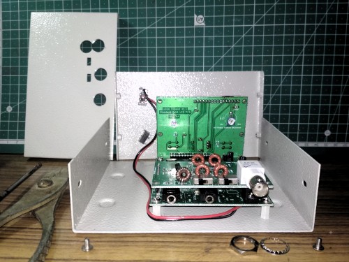
Some enhancement ideas may require you to open the rig. Or you may want to open the cover, just to have a look inside. The cabinet of the rig has a top cover, bottom cover, front panel and rear panel - altogether four pieces of metal parts fixed together with four screws on each side. The motherboard is mounted on the bottom cover. The daughter boards are plugged into the motherboard and also held together with the front and rear panels by the nut of the encoder on the front and the nut of the antenna socket on the rear. So care has to be taken not to put pressure on the mating mechanism between the PCBs, while attempting to open the rig.
You can open the top cover, without disturbing the front and back panels. Out of the four screws on each side, open only the top two screws on each side carefully. This will allow the top cover to be removed without disturbing the front and rear panels. Care should be taken not to put pressure on the front and rear panels causing them to pivot on the bottom screws and slant with respect to the bottom cover. This may exert shearing force on the mating mechanism between the PCBs.
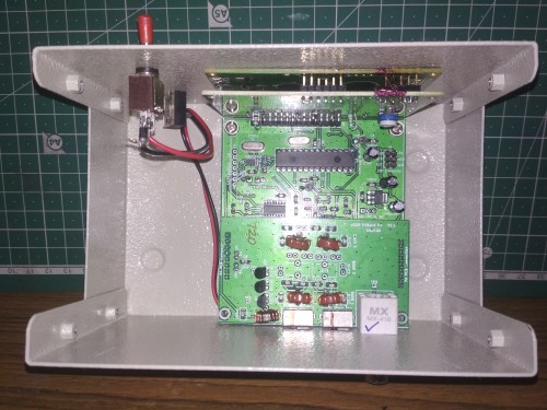
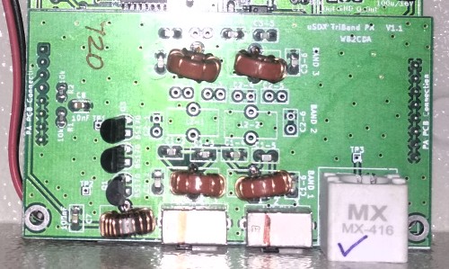
In the above images, the top of the image is towards the front side of the rig.
In the zoomed image of the PA PCB, you can see the unpopulated area of the filters for BAND 2. Here you can add the components required for the band of your choice.
The number 720 you see written on the PCB is the last three digits of the reference frequency for my rig. It had been written at BARC while calibrating the rig's frequency using a good frequency counter. This could vary from rig to rig. If you happen to change the menu setting 8.3 for any reason, you can refer to this number and set it again for correct frequency calibration of your rig.
You can see extra space inside the cabinet on both sides of the PCB. On the left side of the rig (right side of the pic) you can see a narrower space and on the other side you can see voluminous space.You may utilise these spaces in future if you want to.
Below the ON/OFF toggle switch, there is an EP socket on the front panel. On the inside, you can see that the socket is not wired. It can be utilised as per your ideas and requirements.
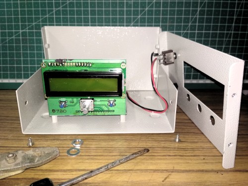
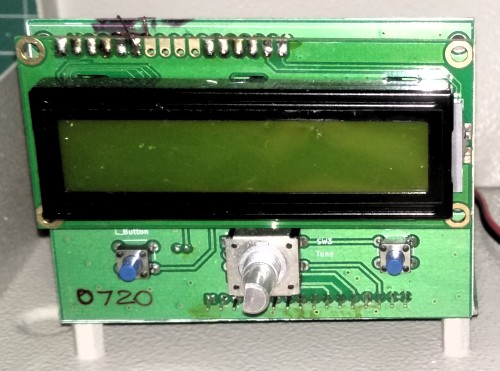
After opening the top cover, carefully loosen and remove the nut and washer on the encoder. This will free the front panel from the LCD PCB, which is still attached to the motherboard. Now you can remove the front bottom screw on each side. After removing the two screws (one on each side), gently remove the front panel. The LCD PCB along with the LCD module should be standing mated to the motherboard.
On the zoomed image you can see the number 0720 written on the LCD PCB. This is the last four digits of the reference frequency setting for my rig. The number may be different on your rig. On the top left of the LCD module, you can see a line of soldered pads. Care to be taken that these points do not touch the front panel metal. The powder coating on the metal panel may provide a layer of insulation, but still if you have any problems with the backlight in spite of setting the option in menu 10.1 to ON, please check if there is a short in this area. This can be solved by covering the soldered points with tape or a piece of thin card board.
With the top cover in removed, carefully loosen and remove the nut and washer on the BNC antenna connector. This will free the rear panel from the PA PCB, which is still attached to the motherboard. Now you can remove the rear bottom screw on each side. After removing the two screws (one on each side), gently remove the rear panel. Now you can see the complete rig's PCB units firmly mounted on the bottom of the cabinet.
