No mechanical modifications are made to the Bird case or cabling so, after this becomes part of my estate, I'll be praised by a future owner for not impacting the resale value. :-)
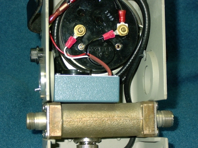
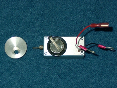
The circuitry is enclosed in a Pomona Electronics #2397 cast aluminum box. A Keystone #106 battery holder is mounted to the removable top of this box. The unit is interfaced to the Bird 43 by means of two crimp-on lugs which attatch to the meter terminals and a single "faston" female terminal which connects to the input from the sensor.
The adapter is mounted by means of a custom made aluminum disk which fits into one of the "slug holders" on the Bird 43. Thanks to Stu's Model Shop for turning this part. The dimensions of the mounting disk are:
Outer lip: 1.25" diameter x .160" wide
Body: 1" diameter x .3125" wide
Switch hole: .25" diameter w/center .425" from the edge and it's
counterbored from the outside with a 15/32" mill bit, .305" deep.
The On-Off switch bushing passes through the side of the box and into the aluminum disk where a 1/4-40 nut fastens the two together. The counterbored hole provides some protecton for the switch acutator which extends only 3/16" beyond the aluminum disk.
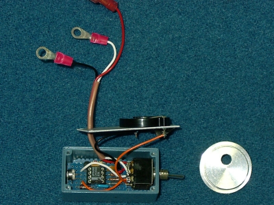
All the circuitry is built on a small piece of perf board. A second small piece of perf board is placed under the completed assembly for insulation. The trimpot is mounted with a 90 degree bend, and secured by a wire loop, so that it may be adjusted through the opposite slug storage hole and a hole in the side of the box. The three interface wires from/to the meter are #22 stranded teflon insulated wire which are bundled together in a short piece of #10 thin wall teflon tubing and pass through a .136" (#29 drill) hole in the top of the box. The single ground run between the meter, sensor and the adapter is not good instrumentation engineering practice but, as the currents involved are soooo tiny, no significant error is introduced.

A National LMC6462 dual micropower op-amp is the heart of this unit. This Op-Amp was chosen, in order of importance, for low offset, rail-to-rail output range, ground included in the input range, though this particular part happens to be rail-to-rail I/O capable, and very low quiescent power. Texas Instruments and Maxim may make some acceptable equivalents. The metal film R's were included to avoid long term drift.
The MBD701 hot carrier diode was employed because it has low reverse leakage, low forward drop and it was handy! A silicon diode may be used as long as it is low leakage. Some of the ubiquitous 1N914/1N4148's are not well controlled in this respect. There may be some "B" versions available that will function acceptably.
The diode across the battery is only included to prevent killing the op-amp should the battery be inadvertently installed backwards. The mid-size 3V lithium coin cell, #2016, should suffice for 3000 hours of operation.
The first section of the Op-amp is configured as a peak detector with gain. The 1.4K input R is to match the Bird's 30uA meter's internal resistance thus providing an equivalent load for the RF sensor. The second amp section is a voltage follower which provides a high impedance sample of the peak voltage. The feedback (gain) loop includes both op-amps and the diode thereby cancelling the diode's forward voltage drop. The small input capacitor prevents the raw RF sample from driving this really slow op-amp crazy. The .1 uf capacitor and 22M resistor set the peak detector time constant at 2.2 seconds. The overall gain is structured so as to protect the meter movement in the event of a circuit fault since the maximum current is limited to about 40uA by the nominal 68K output resistance connected in series with the meter.
This adapter is easily calibrated. A constant RF power is passed thru the Bird coupler to provide 3/4 scale or greater deflection, and the reading is noted with the adapter off. Then, the adapter is turned on and the trimpot is adjusted for an equal reading.

This is an update of the above design which includes a delayed release function plus improved detection of short duration & high modulation rate signals. The overall methodology is the same with the following additions:
Q1 is employed as the peak detector rectifier. Q1's collector current also drives Q2, which discharges C5, reseting the hold time. R4 sets the hold duration.
U2 inverts the level on C5 and drives the current mirror formed by two transistors of U2 which discharges C4, the hold capacitor. R5 sets the release time, by setting the mirror current, which is a constant current so that the meter exhibits a "linear" retrace.
C2 precludes a bit of overshoot which might otherwise be encountered due to the faster Op-Amp employed in this version.
Total power consumption is approx. 1mA at 3 volts.