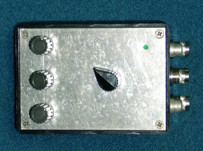
This picture is rotated 90 degrees clockwise to better fit the web page. Normally the three switches at the left are across the lower front of the unit and the following description is written for that orientation.
The 5 position Power / Pulse select switch is upper left. Selections are:The 16 postion Frequency Select switch is at right center.
The pulse / power on indicator (green LED) is at the upper left. It flashes at the selected pulse rate or remains on during continuous wave generation.
The omission of panel markings is a security feature... well, actually no... I have a (long delayed) Quick Basic program in development, for this and other projects, to generate the front panel nomeclature in HPGL code for direct printing on a laser printer
The case is a (4" x 2-7/8" x 1-9/16"hi) bakelite box made by Dakaware (Are they still extant?). Davies makes an equivalent, part no. 220A A new front panel was cut from .062 aluminum to replace the plastic factory piece. 4-40 flathead mounting screws, in countersunk holes, retain the front plate to the box .
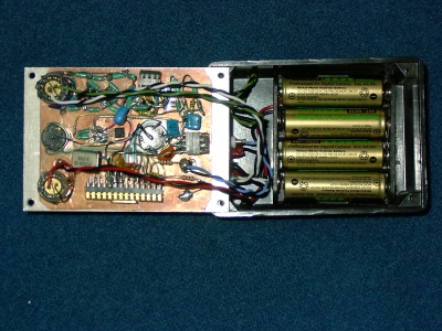
All the circuitry is built on a small piece of PCB material which is retained against the inside of front panel by the four rotary switches The five connectors are mounted on the end of the case. Paralleled BNC & RCA jacks are provided on the In-Phase & Quadrature outputs. The Sync output is a single BNC connector. The unit is powered by 4 internal AA batteries and requires approx. 30 mA. @ 6 volts. The battery holder was fastened to the bottom of the box with foam core double sided tape.
The switches are all Grayhill units:Purchased at retail, these switches are pricey -- totaling around $60 Others may be substituted. Non-encoding types may be used in conjuction with a diode matrix. Lastly, if infrequent adjustment is anticipated, a dip switch may be used in place of both the range & frequency selectors.

A Microchip PIC 16C63 generates, and sums, sine waves digitally, just like a DDS though using only integer steps to prevent distortion. The 16C63 is a now a fairly mature (old!) part. Likely any of the more modern flash PICs that have the serial port and at least 4K of program memory may be substituted. The sine wave data is then serially transmitter to, and converted to analog by, a Crystal CS4333 16 bit Stereo Audio DAC (a part which is normally found in a CD player). The output is low pass filtered and given just a smidge of gain by a dual rail-rail I/O op-amp which connects to the output jacks via a four step (20dB / Step) attenuator. The maximum output level is 0 dBm into 600 ohms. A high impedance load will receive +3 dBm.