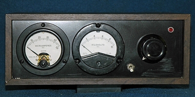
This was my best shot out of many. Hard to take a good pic of this with the white meter scales, black front, and reflective surfaces all confusing the digital camera. The left meter is leakage current directly calibrated in microamperes. The right meter is the output voltage. It is directly calibrated on the 10KV range and must be interpolated at 2X the reading for the 20KV range. It is a 1 mA intrinsic movement. The power/range switch is a 3 postion DPDT with offset operation -- C&K 7211 series. The knob is a General Radio KNSP-8. .
The big insulator is the output voltage terminal. The small insulator is the test voltage return.
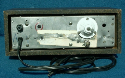
The tester is built with point to point wiring. The case was from an old ON TV (a long defunct over the air subscription service) decoder box. I cut a new aluminum front panel and used the tin plated steel insides "as was".
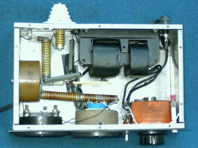
The transformer is a single ended neon type, with one side of the secondary internally connected to the frame, that was donated by a friend -- Thanks, Stu! The variac is a Powerstat type 10A. The HV rectifiers were a house numbered surplus find. The HV resistors with the spiral elements are IRC type MVH-2, 5 megohm. They are tapped for 6-32 threads on the ends so just a short piece of threaded rod makes a quick series assembly and one fits directly into the output insulator.

The Schematic --
The design is fairly straightforward with the variac controlling the output voltage. The test current meter is in the negative side of the test output voltage. The 100K resistor in series with this meter is to protect the movement in the event a voltage source is inadvertantly applied to the return terminal.
The output voltage meter is connected in series with a 10M resistor directly to the output voltage. The 20KV range is calibrated by setting the output to 10KV then setting the range switch to the 20KV range and adjusting P1 for a half scale reading.