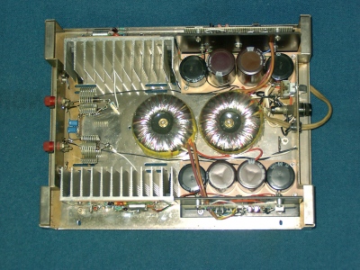
This originally factory wired unit was acquired at a swap meet in a semi "basket case" condtion. All of the transistors had been removed from it; And incidently the decoupling diode to the input stage supply had been installed backwards at some point to poor effect. Rather than replacing all these parts to restore it to the 1960's design, it has been updated to the late 20th century as shown below.
Each channel has an independent power supply. The toroidal transformers may be seen in the center of the unit. The filter capacitors are mounted on PCB material adjacent to the voltage regulators which are each built on one of the old Dynaco "heatsink" plates.
Note that these are constructed with far more substantial heatsinking than the original employed. These heatsinks are common to the negative supply for best heat transfer from the amplifier IC's and are necessarily isolated from the chassis. The output decoupling coils are small lengths of B&W preformed coil stock.
Each channel has an individual toroidal power transformer, rectifier, filter capacitors and dual regulator circuit. The postive regulator is a low dropout design based on a TL431A. The zener diode in series with the TL431A cathode extends its voltage capability. The pass FET gate drive is derived from a voltage doubler. The output of this supply is adjustable between 30 and 32.5 volts with the values shown.
The negative regulator is a tracking low dropout design utilizing the same type N-Channel FET as the postive regulator.
National LM3886 amplifiers are employed in their "stock" connection for each channel.