
|
Board 1 of the receiver uses two SPST switches for changing bands. Several customers have asked for details on using a rotary switch. The information below gives three options. The first is a rotary switch that replaces the two SPST switches on the front of Board 1. If you don't use a Frequency Counter with the receiver this would be the one to build. The second option combines the two SPST switches with the switching of the AADE frequency counter so the receiver and the counter are switched at the same time. Rotary Switch for the Ham Band receiver with the AADE DFD2 frequency counter |


|
Parts needed: Watch out for the correct connections from the Bandpass and Crystal Filter connections. See below. |

|
A wider view of how it all is connected. The switches on the board can be removed if the rotary switch is used. |

|
The rotary switch has been mounted on Board 1 with two standoffs. The space between the standoffs just accepts a standard size rotary switch. Notice the wiring to the switch and the connections on the board. A stack of four standoffs giving a clearance of 1 3/4" is needed to provide clearance for the rotary switch. A smaller diameter rotary switch would provide more clearance so fewer spacers would be needed. A stack of four 5/8" spacers were used between Board 1 and Board 2 in the picture. The kit only supplies a stack of three spacers between Board 1 and 2, so if you are purchasing a rotary switch for this purpose, find a smaller diameter rotary switch than the one used in the pictures. Back to Jumpers, Switches, and Controls, Board 1 Back to Mounting the Boards, Adjustments and Tuning - Testing Board 1Back to Mounting the Boards, Adjustments and Tuning - Tuning and Using the Receiver |


|
The easiest way to build the circuit is "dead bug" style with high megohm resistors used as tie points for wires going to the frequency counter, board 1, and a 4 position rotary switch. Note the "NO" (normally open), "NC" (normally closed), "Coil", and "C" (common) positions of the relay. A rotary switch with more than 4 positions can be used, just wire up the first 4 positions. Don't forget to run a wire from the common connection of the rotary switch to ground, along with the other wires and grounding on the same PCB board. Parts needed in addition to what is supplied: |
|
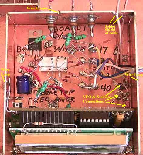
The only difference between the previous picture and this one is the addition of the RF Chokes and Feed-through Capacitors. The RF Chokes are added between the switching circuitry and outside connections. The bottom right of the picture shows the connection of the VFO and Crystal Oscillator signals. Two high megohm resistors are used to terminate the cable leads and then two short wires are run to the appropriate pads on the PCB board. This allows the counter to be removed easily without a lot of wires flopping around. The connections at the resistor stand-offs could be labeled to prevent confusion when wiring to the counter. This is not shown in the picture. If feed-through capacitors are not available, solder a .01 capacitor on the RF Choke and ground just before leaving the box. The 12 Volt and switching pins of the Frequency Counter are connected with RF chokes. The picture below shows all the chokes connected to the Frequency Counter. The next picture shows the chokes connected to the outside connections. Connections to the rotary switch do not use RF Chokes. For a description of all the elements, go to "Elimination of Frequency Counter Birdies". |

|
The lower pins on the bottom left of the picture cannot be seen. Only the ones on the right side are used. The left side pins go to ground. On the RF Choke going to the 12 Volts of the counter there is an extra .0l capacitor (small barrel looking cap) to add extra bypassing. The bare wire going to the PCB ground is soldered to ground underneath the red 12 Volt wire, so it can't be easily seen. |

|
The choke on the left is connected to the input pin (left pin) of the regulator (9 volt shown, but 5 volt works also and is supplied with the present kits). The picture cuts off part of the connection so it cannot all be seen.  Picture shows the wire connecting the Frequency Counter PCB ground plane to the shield box. Wire loops are used around the box to make sure both sides of the PCB sides are grounded.  The shields of the cables bringing the VFO and Crystal Oscillator signals to the frequency counter are grounded on the inside of the box right where they exit. A short length of the other insulation is removed, tinned, and then soldered to the inside of the box. Both cables can be thread through a 1/8" hole. I got lazy and just notched out a place on the top of the board for one of the leads. This adds support to the cables and prevents ground loops that may carry noise.  A close up of the installation of a wire loop. A small piece of bare wire, from a resistor lead cutting, is looped from one side of the PCB to the other. A small notch is made in the PCB just deep enough that the top of the wire loop is level with the top of the board so the top cover of the box will fit snug. It is very important that the connection to the VFO be made at the output of the VFO as shown in the VFO Connection page. If the connection is made at the "Frequency Counter" connection between the VFO amplifiers, the extra drive from that location will overload the frequency counter and generate a lot of birdies. |

|
The connections for the control wires on the back of board 1. These wires are going to the bandpass filter "Gnd for 20/17" circle, and to the crystal filter "Gnd for 30/17" circle. The wires from the circles going to the PCB mounted switches at the front of the board are disconnected. The SPDT switches can be removed from the board.
|
Send E-Mail || Amateur Radio Receivers || Electroluminescent Receiver
