Pulse counters are widely present in everyday
life and it is hard to imagine that one day people will stop using them.
Almost each museum counts visitors, theaters do it as well and in some
urban areas bus line owners count passengers. In industry each production
control includes counting. Usually market tests are performed by counting
sold goods. In sports the quality of a game is shown by attendance. There
are occasions when not only physical values are counted, for example phone
pulses, time measurements etc.
A pulse counter could be roughly divided in three parts. The first part
is a pulses source. The second unit is an electrical device which counts,
memorizes states and prepares results. Finally, the third part is a converter
of electrical states into states available to our senses. Often these
are optical displays.
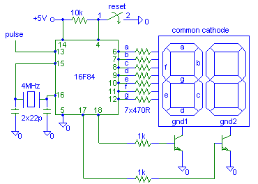
Let’s consider a simple pulse counter controlled by PIC.

Input pulses are TTL logic pulses
(0V, +5V). The ratio impulse/pause is not important, but it is important
that lasting of pause or impulse does not fall below 50us.
Series of pulses are brought to counter, memory and 7 segment converter
integrated in PIC 16F84 (Microchip).
Rising edge of the pulse activates interrupt during which an internal
counter ‘one’ is increased by one. Simultaneously, it is checked
whether the value in the register ‘one’ has not reached 10.
If so, then the register ‘one’ is reset (brought to zero)
and register ‘ten’ increased by one. If the value in the register
‘ten’ reaches 10 it is reset as well and counting starts from
the beginning (procedure next).
During the main program values of ones and tens are showed on a seven
segment display with common cathode. These two numbers are multiplexed
in such a way that PORTB is used for giving a number to the display and
PORTA is used for deciding which display is lit.
Seven segment displays are connected in parallel except of their common
cathodes. The tens cathode (gnd1) is connected via transistor to pin no.
18 and the cathode gnd2 to pin no. 17. In short intervals PIC turns on
one display and turns of the other one. By doing this we get the impression
that both displays are lit simultaneously. Decreasing the multiplexing
rate it is possible to notice dimming of the displays and later on their
blinking.
PIC’s clock is controlled by quartz and it’s very high (1MHz).
For the same purpose we could use RC oscillator, but we should think of
not decreasing the clock too much.
The transistors are necessary, because each PIC’s output can give
up to 25 mA according to Microchip. if we know that a LED could take up
to 50mA and considering the worst case when all seven segments are lit,
we will see that the maximum current could be 350mA. This current could
destroy PIC’s output. Therefore we use transistors which drive little
current from PIC, but allow larger current through the display, for example
BC182 or 2N2222.
To reset the counter it is enough to connect pin no.4 to ground. In this
way the program starts from the address 0 (org 0). This enables us to
reset the counter even if we used four LED displays when there are no
free pins.
To stop the counter simply ‘cut’ the way pulses use to come
to the PIC. Using a separate pin to stop counting is a waste of time and
resources.
Beside the numbers 0-9 it is possible to show some letters: A, C, E, F,
H, J, L, N, P and U.
| Listing 1 |
PROCESSOR 16F84 |
[ About
me | Acronyms | CW
| Data Sheets | Docs
| Download | E-mail
| HOME | Ham
projects | Hobby
circuits | Photo galery
| PIC | QTH
photos |
Sign
in my guestbook | View
my guestbook ]
© 2001 - YO5OFH, Csaba Gajdos