Alinco DR-235TMKIII Page
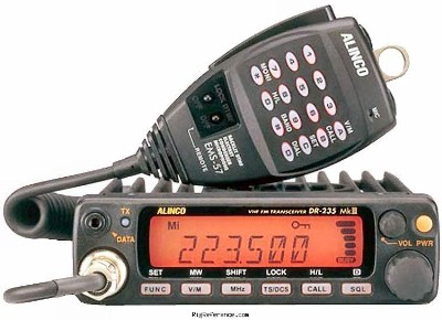
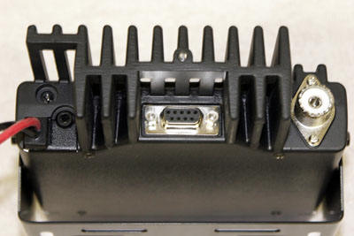
Although I do not own one of these radios, I recently had a chance to work with a few of them ... and the Jetstream JT220M mobile. They are both decent 220mhz radios. The Alinco is popular with those needing packet capability; or those wishing to use this radio in a repeater setting... due to the radio having a rear mounted DB9 connector (that has TX mod, RX audio, COR, and PTT signals present). I think it great that Alinco chose the DB9 format; as it's a very common connector.
HEAVY Transmit Modulation
One thing I noticed with the Alinco was how heavy the transmit modulation was; extremely high gain. Clipping of the transmit audio was easy to accomplish, and a slight distortion could be heard as well. Though the Jetstream radios modulation was normal (and it uses the same microphone as the Alinco). Fixing this is easy; below are the details of my modification to the microphone.
Note: the actual problem is not in the microhpone (more on this at the end of the page); but reducing the TX modulation gain is easiest to take care of within the microphone.
All that needs done is a resistor placed across the mic element - to reduce it's gain. Remove 3 screws from the back of the microphone and sepearte the case halves:. In the upper corner is the underside of the mic element:
take either a 2.2k (red-red-red) or a 3.3k (orange-orange-red) 1/4 watt resistor and fashion it's leads as shown:
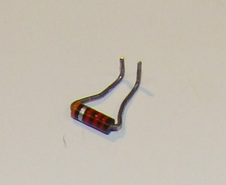
pre-tin the short 90 degree bend portions of the resistor - with a light coating of solder. The resistor above is upside-down from the orientation in which it will be installed.
Which value resistor should you use ??? Here's my recommendation: if the radio is installed in a vehicle (or any noisy environment)... I'd use a 2.2k. If the radio is being operated as a base-station (or any quiet environment)... I'd use the 3.3k value.
Using NeedleNose pliers, hold the resistor in position and solder the leads directly to the mic element solder pads:
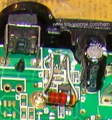
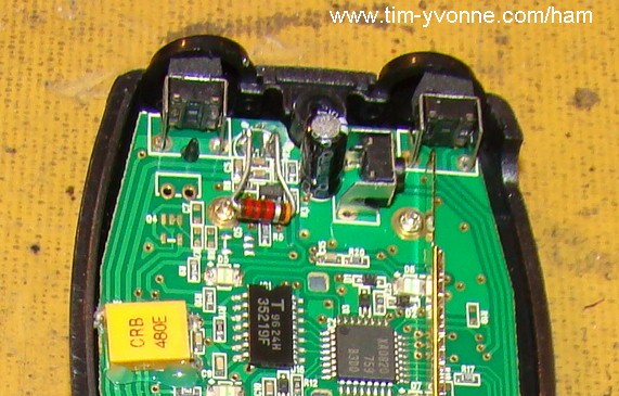
You don't want any portion of the resistor leads to touch anything else. Even though it looks - in the picture above - that one of the leads is touching the head of a screw... it is not (it just looks that way).
It's even easier to use a surface-mount resistor. Just lay it between the mic element pins and solder.
Not The Microphones Fault
"the actual problem is not in the microhpone; but reducing the TX modulation gain is easiest to take care of within the microphone."
The Jetstream JT220M radio uses the same exact microphone as the Alinco. And while I had both model radios on my bench - and before making any microphone modifications - I moved a "loud" factory fresh Alinco microphone over to the Jetstream radio... and it was not heavy on the modulation; it sounded as good as with the Jetstream mic. So, the problem is within the Alinco radio; but modifying the microphone is the easier path to reducing the excessive gain.
There is a "Mic Gain' adjustment...
For those not wanting to modify the microphone... inside the radio is the "VR106" control (labeled"Mic Gain" in the service manual). You can attempt to reduce the gain by adjusting this control - and not modifying the microphone.
Poor Receive and/or Distorted Receive Audio
If all of a sudden the receiver seems to be weak, or the receive audio sounds distorted, check to see if you accidentally placed the radio in the Packet-Digital Voice mode. If the radio is in this mode, you'll see a digital icon at the upper right corner of the display:

exit this mode by pressing and releasing the FUNC key, then pressing and releasing the SQL button.
or
If the radio is in the AM mode, you'll see a "A" at the upper left area of the display:

exit this mode by pressing and releasing the FUNC key, then pressing and releasing the SQL button.
You should have neither the Digital - nor "A" icon on the display. Repeated pressing of the FUNC - SQL button sequence will eventually take you to where neither are showing.
email Tim