|
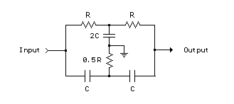
RC Notch Filter (Twin T) The twin T notch filter
can be used block an unwanted frequency or if placed around an op-amp as
a bandpass
Whistle On - Whistle Off
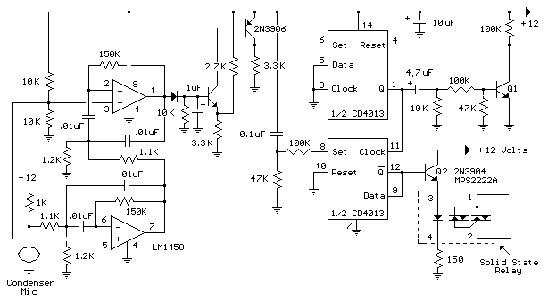
This is an extension of the CMOS toggle flip flop circuit shown in the "Circuits controlling relays" section with the addition of two bandpass filters and condenser microphone so the relay can be toggled by whistling at it. The condender mic used is a PC board mount Radio Shack #270-090C. The filters are tuned to about 1700 Hz, or the third Ab above middle C on a piano keyboard which is a fairly easy note for me to whistle. Resistor values for the filter can be computed using the three formulas below but we need to assume a gain and Q factor for the filter and the Q of the circuit must be greater than the square root of (Gain/2). The microphone produces only a couple millivolts so the overall gain needs to be around 4000 or around 65 for each filter. The Q or quality factor is the ratio of the center frequency to the bandwidth (-3dB points) and was chosen to be 8 which is greater than 5.7 which is the minimum value for a gain of 65. Both capacitor values need to be the same for easy computation of the resistor values and were chosen to be 0.01uF which is a common value and usable at audio frequencies. From those assumptions, the resistor values can be worked out from the following formulas. R1 = Q/(G*C*2*Pi*F) =
8/(65*.01^-6*6.28*1700) = 1152 or 1.1K The op-amps are biased
using a voltage divider of two 10K resistors so the output will be
centered around half the supply voltage or 6 volts. The output of the
second filter charges a 1uF cap at the base of a NPN transistor (2N3904 or
similar). The emitter voltage is biased at 6.6 volts using the 3.3K and
2.7K resistors so that the transistor will conduct and trigger the flip
flop when the peak signal from the filter reaches 8 volts. The 8 volt
figure is the emitter voltage (6.6) plus the emitter base voltage drop
(0.7) plus the diode drop (0.7). The sensitivity can be adjusted by
changing the value of either the 2.7K or 3.3K resistors so that more or
less signal amplitude is needed to trigger the flop flop.
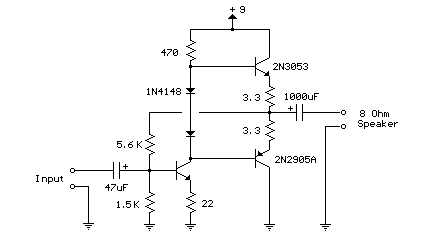
Here is a little audio
amplifier similar to what you might find in a small transistor radio. The
input stage is biased
Ham radio Data Center - free schematics | 73s.eu - Free Ham Radio Social Network | Free HAM Directory | About me | Acronyms | CW | Data Sheets | Docs | Download | E-mail | HOME | Ham projects | Hobby circuits | Photo galery | PIC | QTH photos | © 2001 - YO5OFH, Csaba Gajdos |

 filter. The notch frequency occurs where the capacitive reactance equals
the resistance (Xc=R) and if the values are close, the attenuation can
be very high and the notch frequency virtually eliminated. The insertion
loss of the filter will depend on the load that is connected to the
output, so the resistors should be of much lower value than the load for
minimal loss. At audio frequencies, the filter could function as a bass
and treble boost circuit by attenuating the mid range frequencies. Using
1.5K resistors and 0.1uF capacitors, the band stop at -10dB is about 500
Hz to 2Khz. The depth and width of the response can be adjusted somewhat
with the 0.5R value and by adding some resistance across the C values.
If the circuit is used around an op-amp as a bandpass filter, the
response may need to be dampened to avoid oscillation.
 so that the supply voltage is divided equally across the two complimentary
output transistors which are slightly biased in conduction by the diodes
between the bases. A 3.3 ohm resistor is used in series with the emitters
of the output transistors to stabilize the bias current so it doesn't
change much with temperature or with different transistors and diodes. As
the bias current increases, the voltage between the emitter and base
decreases, thus reducing the conduction. Input impedance is about 500 ohms
and voltage gain is about 5 with an 8 ohm speaker attached. The voltage
swing on the speaker is about 2 volts without distorting and power output
is in the 50 milliwatt range. A higher supply voltage and the addition of
heat sinks to the output transistors would provide more power. Circuit
draws about 30 milliamps from a 9 volt supply.