|
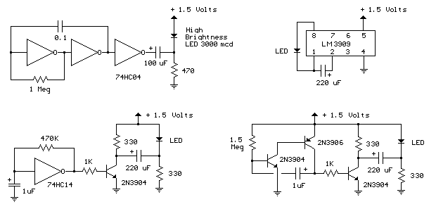
1.5 Volt LED Flashers The LED flasher circuits below operate on a single 1.5 volt battery. The circuit on the upper right uses the popular LM3909 LED flasher IC and requires only a timing capacitor and LED.
The top left circuit, designed by Andre De-Guerin illustrates using a 100uF capacitor to double the battery voltage to obtain 3 volts for the LED. Two sections of a 74HC04 hex inverter are used as a squarewave oscillator that establishes the flash rate while a third section is used as a buffer that charges the capacitor in series with a 470 ohm resistor while the buffer output is at +1.5 volts. When the buffer output switches to ground (zero volts) the charged capacitor is placed in series with the LED and the battery which supplies enough voltage to illuminate the LED. The LED current is approximately 3 mA, so a high brightness LED is recommended. In the other two circuits, the same voltage doubling
principle is used with the addition of a transistor to allow the
capacitor to discharge faster and supply a greater current (about 40 mA
peak). A larger capacitor (1000uF) in series with a 33 ohm resistor
would increase the flash duration to about 50mS. The discrete 3
transistor circuit at the lower right would need a resistor (about 5K)
in series with the 1uF capacitor to widen the pulse width.
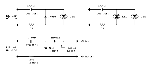
AC Line powered
LEDs The circuit below illustrats powering a LED (or two) from the 120 volt AC line using a capacitor to drop the voltage and a small resistor to limit the inrush current. Since the capacitor must pass current in both directions, a small diode is connected in parallel with the LED to provide a path for the negative half cycle and also to limit the reverse voltage across the LED. A second LED with the polarity reversed may be subsituted for the diode, or a tri-color LED could be used which would appear orange with alternating current. The circuit is fairly efficient and draws only about a half watt from the line. The resistor value (1K / half watt) was chosen to limit the worst case inrush current to about 150 mA which will drop to less than 30 mA in a millisecond as the capacitor charges. This appears be a safe value, I have switched the circuit on and off many times without damage to the LED. The 0.47 uF capacitor has a reactance of 5600 ohms at 60 cycles so the LED current is about 20 mA half wave, or 10 mA average. A larger capacitor will increase the current and a smaller one will reduce it. The capacitor must be a non-polarized type with a voltage rating of 200 volts or more. The lower circuit is an example of obtaining a low
regulated voltage from the AC line. The zener diode serves as a
regulator and also provides a path for the negative half cycle current
when it conducts in the forward direction. In this example the output
voltage is about 5 volts and will provide over 30 milliamps with about
300 millivolts of ripple. Use caution when operating any circuits
connected directly to the AC line.
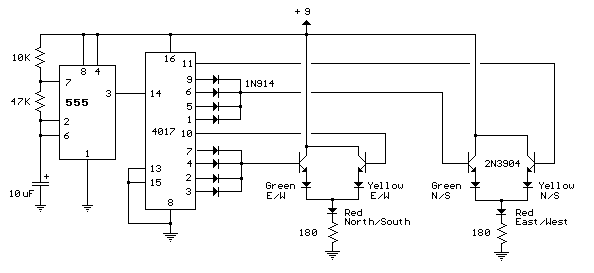
LED Traffic Lights The LED traffic Light circuit controls 6 LEDs (red,
yellow and green) for both north/south directions and east/west
directions. The timing sequence is generated using a CMOS 4017 decade
counter and a 555 timer. Counter outputs 1 through 4 are wire ORed using 4
diodes so that the (Red - North/South) and (Green - East/West) LEDs will
be on during the first four counts. The fifth count (pin 10) illuminates
(Yellow - East/West) and (Red - North/South). Counts 6 through 9 are also
wire ORed using diodes to control (Red - East/West) and (Green -
North/South). Count 10 (pin 11) controls (Red - East/West) and (Yellow -
North/South). The time period for the red and green lamps will be 4 times
longer than for the yellow and the complete cycle time can be adjusted
with the 47K resistor. The eight 1N914 diodes could be subsituted with a
dual 4 input OR gate (CD4072).
40 LED Bicycle Light
16 Stage Bi-Directional
LED Sequencer
|
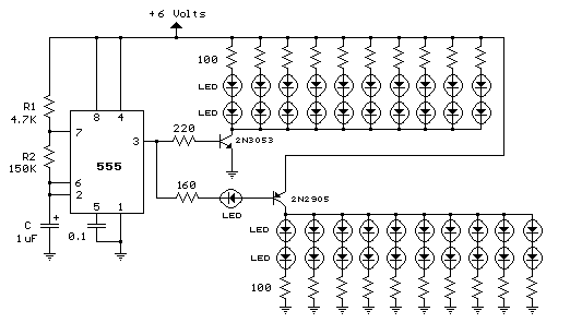 The
555 circuit below is a flashing bicycle light powered with four C,D or AA
cells (6 volts). Two sets of 20 LEDs will alternately flash at
approximately 4.7 cycles per second using RC values shown (4.7K for R1,
150K for R2 and a 1uF capacitor). Time intervals for the two lamps are
about 107 milliseconds (T1, upper LEDs) and 104 milliseconds (T2 lower
LEDs). Two transistors are used to provide additional current beyond the
200 mA limit of the 555 timer. A single LED is placed in series with the
base of the PNP transistor so that the lower 20 LEDs turn off when the 555
output goes high during the T1 time interval. The high output level of the
555 timer is 1.7 volts less than the supply voltage. Adding the LED
increases the forward voltage required for the PNP transistor to about 2.7
volts so that the 1.7 volt difference from supply to the output is
insufficient to turn on the transistor. Each LED is supplied with about 20
mA of current for a total of 220 mA. The circuit should work with
additional LEDs up to about 40 for each group, or 81 total. The circuit
will also work with fewer LEDs so it could be assembled and tested with
just 5 LEDs (two groups of two plus one) before adding the others.
The
555 circuit below is a flashing bicycle light powered with four C,D or AA
cells (6 volts). Two sets of 20 LEDs will alternately flash at
approximately 4.7 cycles per second using RC values shown (4.7K for R1,
150K for R2 and a 1uF capacitor). Time intervals for the two lamps are
about 107 milliseconds (T1, upper LEDs) and 104 milliseconds (T2 lower
LEDs). Two transistors are used to provide additional current beyond the
200 mA limit of the 555 timer. A single LED is placed in series with the
base of the PNP transistor so that the lower 20 LEDs turn off when the 555
output goes high during the T1 time interval. The high output level of the
555 timer is 1.7 volts less than the supply voltage. Adding the LED
increases the forward voltage required for the PNP transistor to about 2.7
volts so that the 1.7 volt difference from supply to the output is
insufficient to turn on the transistor. Each LED is supplied with about 20
mA of current for a total of 220 mA. The circuit should work with
additional LEDs up to about 40 for each group, or 81 total. The circuit
will also work with fewer LEDs so it could be assembled and tested with
just 5 LEDs (two groups of two plus one) before adding the others.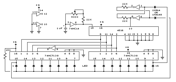 (74HC138 or 74HCT138) to generate the popular "Night Rider"
display. A Schmitt Trigger oscillator provides the clock signal for the
counter and the rate can be adjusted with the 500K pot. Two additional
Schmitt Trigger inverters are used as a SET/RESET latch to control the
counting direction (up or down). Be sure to use the 74HC14 and not the
74HCT14, the 74HCT14 may not work due to the low TTL input trigger level.
When the highest count is reached (1111) the low output at pin 7 sets the
latch so that the UP/DOWN input to the counter goes low and causes the
counter to begin decrementing. When the lowest count is reached (0000) the
latch is reset (high) so that the counter will begin incrementing on the
next rising clock edge. The three lowest counter bits (Q0, Q1, Q2) are
connected to both decoders in parallel and the highest bit Q3 is used to
select the appropriate decoder. The circuit can be used to drive 12
volt/25 watt lamps with the addition of two transistors per lamp as shown
below in the section below titled "Interfacing 5 volt CMOS to 12 volt
loads".
(74HC138 or 74HCT138) to generate the popular "Night Rider"
display. A Schmitt Trigger oscillator provides the clock signal for the
counter and the rate can be adjusted with the 500K pot. Two additional
Schmitt Trigger inverters are used as a SET/RESET latch to control the
counting direction (up or down). Be sure to use the 74HC14 and not the
74HCT14, the 74HCT14 may not work due to the low TTL input trigger level.
When the highest count is reached (1111) the low output at pin 7 sets the
latch so that the UP/DOWN input to the counter goes low and causes the
counter to begin decrementing. When the lowest count is reached (0000) the
latch is reset (high) so that the counter will begin incrementing on the
next rising clock edge. The three lowest counter bits (Q0, Q1, Q2) are
connected to both decoders in parallel and the highest bit Q3 is used to
select the appropriate decoder. The circuit can be used to drive 12
volt/25 watt lamps with the addition of two transistors per lamp as shown
below in the section below titled "Interfacing 5 volt CMOS to 12 volt
loads".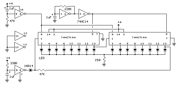 registers (74HCT164 or 74HC164) to sequence 16 LEDs. The circuit can be
expanded to greater lengths by cascading additional shift registers and
connecting the 8th output (pin 13) to the data input (pin 1) of the
succeeding stage. A Schmitt trigger oscillator (74HC14 pin 1 and 2)
produces the clock signal for the shift registers, the rate being
approximately 1/RC. Two additional Schmitt Trigger stages are used to
reset and load the registers when power is turned on. Timing is not
critical, however the output at pin 8 of the Schmitt Trigger must remain
high during the first LOW to HIGH clock transition at pin 8 of the
registers, and must return low before the second rising edge to load a
single bit. If the clock rate is increased, the length of the signal at
pin 9 of the Schmitt Trigger should be reduced proportionally to avoid
loading more than one bit. The HCT devices will normally provide about 4
mA (source or sink) from each output but can supply greater currents
(possibly 25 mA) if only one output is loaded. The common 150 ohm resistor
restricts the current below 25 mA using a 6 volt power source. If the
circuit is operated with two or more LEDs on at the same time, resistors
may be needed in series with each LED to avoid exceeding the maximum total
output current for each IC of 25 mA. For greater brightness, individual
buffer transistors can be used as shown in the 10 stage LED sequencer on
this same page.
registers (74HCT164 or 74HC164) to sequence 16 LEDs. The circuit can be
expanded to greater lengths by cascading additional shift registers and
connecting the 8th output (pin 13) to the data input (pin 1) of the
succeeding stage. A Schmitt trigger oscillator (74HC14 pin 1 and 2)
produces the clock signal for the shift registers, the rate being
approximately 1/RC. Two additional Schmitt Trigger stages are used to
reset and load the registers when power is turned on. Timing is not
critical, however the output at pin 8 of the Schmitt Trigger must remain
high during the first LOW to HIGH clock transition at pin 8 of the
registers, and must return low before the second rising edge to load a
single bit. If the clock rate is increased, the length of the signal at
pin 9 of the Schmitt Trigger should be reduced proportionally to avoid
loading more than one bit. The HCT devices will normally provide about 4
mA (source or sink) from each output but can supply greater currents
(possibly 25 mA) if only one output is loaded. The common 150 ohm resistor
restricts the current below 25 mA using a 6 volt power source. If the
circuit is operated with two or more LEDs on at the same time, resistors
may be needed in series with each LED to avoid exceeding the maximum total
output current for each IC of 25 mA. For greater brightness, individual
buffer transistors can be used as shown in the 10 stage LED sequencer on
this same page.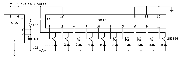
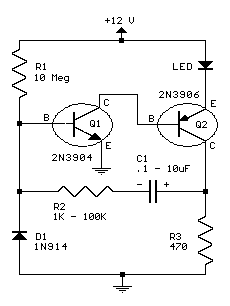 This circuit will flash a bright red LED
(5000 mcd) as an attention getting device or fake car alarm. Component
values are not critical and other transistors may be used. Flash duration
is determined by R2 and C1 and is approximately 3 time constants
(3*R2*C1). Brightness is controlled by R3 wich limits the LED current to
about 20 mA for values listed. R1 provides bias for the transistors which
should be low enough not to saturate Q2 with the capacitor disconnected.
If the circuit does not oscillate, R1 may be too low or R2 may be too
high. D1 allows for higher duty cycle operation and limits the reverse
voltage at the base of Q1 to -0.7 V. D1 may be omitted for low voltage
(3-9) and low duty cycle operation. Most parts available at Radio Shack.
This circuit will flash a bright red LED
(5000 mcd) as an attention getting device or fake car alarm. Component
values are not critical and other transistors may be used. Flash duration
is determined by R2 and C1 and is approximately 3 time constants
(3*R2*C1). Brightness is controlled by R3 wich limits the LED current to
about 20 mA for values listed. R1 provides bias for the transistors which
should be low enough not to saturate Q2 with the capacitor disconnected.
If the circuit does not oscillate, R1 may be too low or R2 may be too
high. D1 allows for higher duty cycle operation and limits the reverse
voltage at the base of Q1 to -0.7 V. D1 may be omitted for low voltage
(3-9) and low duty cycle operation. Most parts available at Radio Shack.| Volts | R1 | R2 | R3 | C1 | Approx. Flash Rate |
|---|---|---|---|---|---|
| 12 | 10 Mohm | 22 Kohm | 470 ohm | 0.47 uF | 140 per minute |
| 12 | 10 Mohm | 10 Kohm | 470 ohm | 1 uF | 60 per minute |
| 9 | 6.8 Mohm | 1 Kohm | 390 ohm | 6.8 uF | 15 per minute |
| 6 | 3.3 Mohm | 10 Kohm | 220 ohm | 1 uF | 80 per minute |
| 3 | 1.5 Mohm | 10 Kohm | 51 ohm | 1 uF | 120 per minute |
| 3 | 3.3 Mohm | 47 Kohm | 51 ohm | 0.47 uF | 140 per minute |
Fading Red Eyes
![]()
This circuit can be used
to slowly illuminate and fade a pair of red LEDs. A linear 3 volt p-p
ramping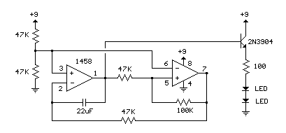 wavform is generated at pin 1 of the IC and buffered with an emitter
follower transistor stage. The 22uF capacitor and 47K resistor connected
to pin 2 establish the frequency which is about 0.5 Hz.
wavform is generated at pin 1 of the IC and buffered with an emitter
follower transistor stage. The 22uF capacitor and 47K resistor connected
to pin 2 establish the frequency which is about 0.5 Hz.
Original scheme edited by Bill
Bowden, http://www.bowdenshobbycircuits.info
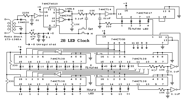
28 LED Clock Timer
![]()
Original scheme edited by Bill
Bowden, http://www.bowdenshobbycircuits.info
This is a programmable
clock timer circuit that uses individual LEDs to indicate hours and
minutes. 12 LEDs can be arranged in a circle to represent the 12 hours of
a clock face and an additional 12 LEDs can be arranged in an outer circle
to indicate 5 minute intervals within the hour. 4 additional LEDs are used
to indicate 1 to 4 minutes of time within each 5 minute interval.
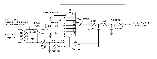
The circuit is powered from a small 12.6 volt center tapped line
transformer and the 60 cycle line frequency is used for the time base. The
transformer is connected in a full wave, center tapped configuration which
produces about 8.5 volts unregulated DC. A 47 ohm resistor and 5.1 volt, 1
watt zener regulate the supply for the 74HCT circuits.
A 14 stage 74HCT4020 binary counter and two NAND gates are used to divide
the line frequency by 3600 producing a one minute pulse which is used to
reset the counter and advance the 4017 decade counter. The decade counter
counts the minutes from 0 to 4 and resets on the fifth count or every 5
minutes which advances one section of a dual 4 bit binary counter
(74HCT393). The 4 bits of this counter are then decoded into one of 12
outputs by two 74HCT138 (3 line to 8 line) decoder circuits. The most
significant bit is used in conjunction with an inverter to select the
appropriate decoder. During the first eight counts, the low state of the
MSB is inverted to supply a high level to enable the decoder that drives
the first 8 LEDs. During counts 9 to 12, the MSB will be high and will
select the decoder that drives the remaining 4 LEDs while disabling the
other decoder. The decoded outputs are low when selected and the 12 LEDs
are connected common anode with a 330 ohm current limiting resistor to the
+5 volt supply. The 5th output of the second decoder (pin 11) is used to
reset the binary counter so that it counts to 11 and then resets to zero
on the 12th count. A high reset level is required for the 393 counters, so
the low output from the last decoder stage (pin 11) is inverted with one
section of a 74HCT14 hex Schmitt trigger inverter circuit. A 10K resistor
and 0.1uF cap are used to extend the reset time, ensuring the counter
receives a reset signal which is much longer than the minimum time
required. The reset signal is also connected to the clock input (pin 13)
of the second 4 bit counter (1/2 74HCT393) which advances the hour LEDs
and resets on the 12th hour in a similar manner.
Setting the correct time is accomplished with two manual push buttons
which feed the Q4 stage (pin 7) of the 4020 counter to the minute and hour
reset circuits which advance the counters at 3.75 counts per second. A
slower rate can be obtained by using the Q5 or Q6 stages. For test
purposes, you can use Q1 (pin 9) which will advance the minutes at 30 per
second.
The time interval circuit (shown below the clock) consists of a SET/RESET
flipflop made from the two remaining NAND gates (74HCT00). The desired
time interval is programmed by connecting the anodes of the six diodes
labeled start, stop and AM/PM to the appropriate decoder outputs. For
example, to turn the relay on at 7:05AM and turn it off at 8:05AM, you
would connect one of the diodes from the start section to the cathode of
the LED that represents 7 hours, the second diode to the LED cathode that
represents 5 minutes and the third diode to the AM line of the CD4013. The
stop time is programmed in the same manner. Two additional push buttons
are used to manually open and close the relay. The low start and stop
signals at the common cathode connections are capacitively coupled to the
NAND gates so that the manual push buttons can override the 5 minute time
duration. That way, you can immediately reset the relay without waiting 5
minutes for the start signal to go away.
The two power supply rectifier diodes are 1N400X variety and the switching
diodes are 1N914 or 4148s but any general purpose diodes can be used. 0.1
uF caps (not shown on schematic) may be needed near the power pins of each
IC. All parts should be available from Radio Shack with the exception of
the 74HCT4017 decade counter which I didn't see listed. You can use either
74HC or 74HCT parts, the only difference between the two is that the input
switching levels of the HCT devices are compatible with worst case TTL
logic outputs. The HC device inputs are set at 50% of Vcc, so they may not
work when driven from marginal TTL logic outputs. You can use a regular
4017 in place of the 74HCT4017 but the output current will much lower
(less than 1 mA) and 4 additional transistors will be required to drive
the LEDs. Without the buffer transistors, you can use a 10K resistor in
place of the 330 and the LEDs will be visible, but very dim. Using the
4017 to drive LEDs with transistor buffers is shown in the "10
Channel LED Sequencer" at the top of this page.
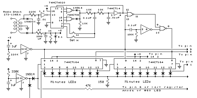
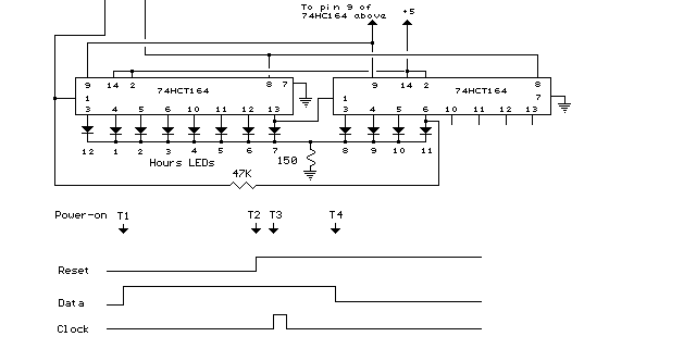
72 LED Clock
![]()
Original scheme edited by Bill
Bowden, http://www.bowdenshobbycircuits.info
In the circuit below, 60 individual LEDs are used to indicate the minutes of a clock and 12 LEDs indicate hours. The power supply and time base circuitry is the same as described in the 28 LED clock circuit above. The minutes section of the clock is comprised of eight 74HCT164 shift registers cascaded so that a single bit can be recirculated through the 60 stages indicating the appropriate minute of the hour. Only two of the minutes shift registers are shown connected to 16 LEDs. Pin 13 of each register connects to pin 1 of the next for 7 registers. Pin 6 of the 8th register should connect back to pin 1 of the first register using the 47K resistor. Pins 2,9,8, 14 and 7 of all 8 minutes registers (74HC164) should be connected in parallel (pin 8 to pin 8, pin 9 to pin 9, etc.). The hours section contains two 8 bit shift registers and works the same way as the minutes to display 1 of 12 hours. Pin 9 of all 74HCT164s (hours and minutes) should be connected together. For 50 Hertz operation, the time base section of the circuit can be modified as shown in the lower drawing labeled "50 Hertz LED Clock Time Base". You will need an extra IC (74HC30) to do this since it requires decoding 7 bits of the counter instead of 4. The two dual input NAND gates (1/2 74HC00) that are not used in the 50 Hertz modification should have their inputs connected to ground.
When power is applied, a single "1" bit is loaded into the first stage of both the minutes and hours registers. To accomplish this, a momentary low reset signal is sent to all the registers (at pin 9) and also a NAND gate to lock out any clock transitions at pin 8 of the minutes registers. At the same time, a high level is applied to the data input lines of both minutes and hours registers at pin 1. A single positive going clock pulse (at pin 8) is generated at the end of the reset signal which loads a high level into the first stage of the minutes register. The rising edge of first stage output at pin 3 advances the hours (at pin 8) and a single bit is also loaded into the hours register. Power should remain off for about 3 seconds or more before being re-applied to allow the filter and timing capacitors to discharge. A 1K bleeder resistor is used across the 1000uF filter capacitor to discharge it in about 3 seconds. The timing diagram illustrates the power-on sequence where T1 is the time power is applied and beginning of the reset signal, T2 is the end of the reset signal, T3 is the clock signal to move a high level at pin 1 into the first register, T4 is the end of the data signal. The time delay from T2 to T3 is exaggerated in the drawing and is actually a very short time of just the propagation delay through the inverter and gate.
Two momentary push buttons can be used to set the correct time. The button labeled "M" will increment the minutes slowly and the one labled "H" much faster so that the hours increment slowly. The hours should be set first, followed by minutes.
50 Hertz LED Clock
Timebase

Original scheme edited by Bill
Bowden, http://www.bowdenshobbycircuits.info
Infrared Remote Control
Tester
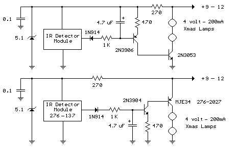 This
is a fairly easy circuit that can be used to test TV and VCR remote
controls. The infrared detector module (GP1U52X) (Radio Shack 276-137)
produces a 5 volt TTL pulse train corresponding to the digital code of the
particular remote control key pressed. In the lower circuit, the module
output is normally low with no signal received and becomes a positive
going pulse train when a signal is present. Other detector modules are
available that have an inverted output as shown in the upper drawing which
is the type I used, but I don't have the part number, I believe it was
removed from a VCR. The pulse sequence represents the digital code of the
particular key pressed along with possible manufacturer information. As
the pulse train occurs, the 4.7uF capacitor is charged to about 3 volts
and the capacitor voltage minus a diode drop appears across the 470 ohm
resistor yielding a collector current from the 2N3904 or 2N3906 of about 5
milliamps. The collector current of the first stage flows into the base of
the output transistor (MJE34 or 2N3053) which delivers around 250 mA into
the indicator lamps. When the pulse train ends, the capacitor slowly
discharges through the base of the first stage transistor allowing the
Xmas tree lights to remain on for a about 1 second. The little Xmas lamps
will operate over a wide voltage range, so you can use bulbs from almost
any string, but bulbs from shorter strings (35 or less) will probably last
longer operated at 5 volts.
This
is a fairly easy circuit that can be used to test TV and VCR remote
controls. The infrared detector module (GP1U52X) (Radio Shack 276-137)
produces a 5 volt TTL pulse train corresponding to the digital code of the
particular remote control key pressed. In the lower circuit, the module
output is normally low with no signal received and becomes a positive
going pulse train when a signal is present. Other detector modules are
available that have an inverted output as shown in the upper drawing which
is the type I used, but I don't have the part number, I believe it was
removed from a VCR. The pulse sequence represents the digital code of the
particular key pressed along with possible manufacturer information. As
the pulse train occurs, the 4.7uF capacitor is charged to about 3 volts
and the capacitor voltage minus a diode drop appears across the 470 ohm
resistor yielding a collector current from the 2N3904 or 2N3906 of about 5
milliamps. The collector current of the first stage flows into the base of
the output transistor (MJE34 or 2N3053) which delivers around 250 mA into
the indicator lamps. When the pulse train ends, the capacitor slowly
discharges through the base of the first stage transistor allowing the
Xmas tree lights to remain on for a about 1 second. The little Xmas lamps
will operate over a wide voltage range, so you can use bulbs from almost
any string, but bulbs from shorter strings (35 or less) will probably last
longer operated at 5 volts.
The circuit can be
powered from a small 9-12 volt DC, 250 mA or greater wall transformer. It
may also need an additional 1000 uF filter capacitor across the DC output
if the wall transformer does not have a built in capacitor. For use with a
9 volt battery, the incandescent lamps can be replaced with a regular LED
and 680 ohm resistor and the output transistors can be replaced with small
signal transistors (2N3904 or 2N3906). The total current drain will be
about 25 mA with the LED lit, and 15 mA standby when the LED is off.
Original scheme edited by Bill
Bowden, http://www.bowdenshobbycircuits.info
Battery Equal Charge
Indicator
The circuit below
illuminates an LED to indicate unequal charges between two 12 volt lead
batteries. It can be used to verify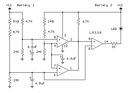 that two batteries are connected in parallel or isolated since the LED
will be off when the voltages are equal within a tollerance, or on if the
voltage difference is greater than 100 millivolts. Three comparators and
three voltage dividers are used to determine battery conditions. The upper
left comparator (+) input at pin 5 is set to about 10 volts with battery
#1 at 12 volts. The negative input (pin 4) is set to a slightly lower
voltage by adding an additional 240 ohms to the voltage divider so that
the output of the comparator will be positive when both battery voltages
are equal and negative if battery 2 rises above battery 1 by 100
millivolts or more. The voltage at pin 5 is used as a reference for the
lower comparator and the negative input of the lower comparator is set to
a lower voltage with the addition of 510 ohms, so that the output will
also be positive when the battery voltages are equal and negative when
battery #1 is greater than #2 by 100 millivolts or more. The two
comparator outputs are both connected to the positive input of the third
comparator at pin 9 so that the LED will illuminate when either condition
exists,
that two batteries are connected in parallel or isolated since the LED
will be off when the voltages are equal within a tollerance, or on if the
voltage difference is greater than 100 millivolts. Three comparators and
three voltage dividers are used to determine battery conditions. The upper
left comparator (+) input at pin 5 is set to about 10 volts with battery
#1 at 12 volts. The negative input (pin 4) is set to a slightly lower
voltage by adding an additional 240 ohms to the voltage divider so that
the output of the comparator will be positive when both battery voltages
are equal and negative if battery 2 rises above battery 1 by 100
millivolts or more. The voltage at pin 5 is used as a reference for the
lower comparator and the negative input of the lower comparator is set to
a lower voltage with the addition of 510 ohms, so that the output will
also be positive when the battery voltages are equal and negative when
battery #1 is greater than #2 by 100 millivolts or more. The two
comparator outputs are both connected to the positive input of the third
comparator at pin 9 so that the LED will illuminate when either condition
exists,
(Battery #1 > Battery #2) OR (Battery #2 > Battery #1).
Original scheme edited by Bill
Bowden, http://www.bowdenshobbycircuits.info
Astable Multivibrator
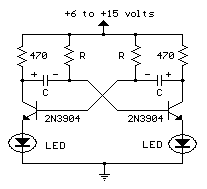
This is an astable multivibrator circuit to alternately
flash two LEDs. The R and C values determine the frequency and the 470ohm
collector load resistor set the current to about 20mA when the circuit is
operated at 12 V. Frequency is about 1 cycle per second using 22uF
capacitors and 47K resistors. Smaller R or C values will increase
frequency. The LEDs may also be vired in series with the collector
resistors and other transistors can be used. Reverse the supply voltage
connections and LED connections if PNP type transistors are used.
Original scheme edited by Bill
Bowden, http://www.bowdenshobbycircuits.info
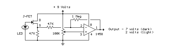
LED Photo Sensor.
Here's a circuit that takes advantage of the photo-voltaic voltage of an ordinary LED. The LED voltage is buffered by a junction FET transistor and then applied to the inverting input of an op-amp with a gain of about 20. This produces a change of about 5 volts at the output from darkness to bright light. The 100K potentiometer can be set so that the output is around 7 volts in darkness and falls to about 2 volts in bright light.
Original scheme edited by Bill
Bowden, http://www.bowdenshobbycircuits.info
Ham radio Data Center - free schematics | 73s.eu - Free Ham Radio Social Network | Free HAM Directory | About me | Acronyms | CW | Data Sheets | Docs | Download | E-mail | HOME | Ham projects | Hobby circuits | Photo galery | PIC | QTH photos |
Sign in my guestbook | View my guestbook ]
© 2001 - YO5OFH, Csaba Gajdos