|

Telephone Ring Generator
Using Switching Supply

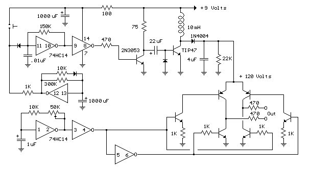 The
telephone ring generator shown below generates the needed high voltage
from a simple switching mode power supply (SMPS) which employs a CMOS
Schmitt Trigger square wave oscillator, 10 mH inductor, high voltage
switching transistor (TIP47 or other high voltage, 1 amp transistor) and a
driver transistor (2N3053). The inductor should have a low DC resistance
of 1.5 ohms or less. The switching supply must have a load connected to
prevent the voltage from rising too high, so a 22K resistor is used across
the output which limits the voltage to about 120 DC with the phone ringer
disconnected and about 90 volts DC connected. The output voltage can be
adjusted by changing the value of the 150K resistor between pins 10 and 11
which will alter the oscillator frequency (frequency is around 800 Hz as
shown). The supply is gated on and off by a second Schmitt Trigger
oscillator (pins 12/13) so that the phone rings for about 2 seconds and
then the circuit idles for about a minute between rings. These times can
be adjusted with the 10K and 300K resistors connected to pin 12. The push
button shown is used to manually ring the phone. The 25Hz ringing
frequency is generated by another Schmitt Trigger oscillator (pins 1/2)
which controls the H bridge transistor output circuit. The 6 transistors
in the output stage (4 NPN, 2 PNP) should be high voltage types rated at
200 volts collector to emitter or more. The ringer will only draw around
10 mA, so the output transistors can have a low current rating but must
have a high voltage rating. I used TIP47s and small signal PNPs of unknown
numbers that I had on hand, but other types such as NTE287 (NPN) and
NTE288 (PNP) should work. Both have a 300 volt C-E rating and cost about
$0.95 from mail order houses. The
telephone ring generator shown below generates the needed high voltage
from a simple switching mode power supply (SMPS) which employs a CMOS
Schmitt Trigger square wave oscillator, 10 mH inductor, high voltage
switching transistor (TIP47 or other high voltage, 1 amp transistor) and a
driver transistor (2N3053). The inductor should have a low DC resistance
of 1.5 ohms or less. The switching supply must have a load connected to
prevent the voltage from rising too high, so a 22K resistor is used across
the output which limits the voltage to about 120 DC with the phone ringer
disconnected and about 90 volts DC connected. The output voltage can be
adjusted by changing the value of the 150K resistor between pins 10 and 11
which will alter the oscillator frequency (frequency is around 800 Hz as
shown). The supply is gated on and off by a second Schmitt Trigger
oscillator (pins 12/13) so that the phone rings for about 2 seconds and
then the circuit idles for about a minute between rings. These times can
be adjusted with the 10K and 300K resistors connected to pin 12. The push
button shown is used to manually ring the phone. The 25Hz ringing
frequency is generated by another Schmitt Trigger oscillator (pins 1/2)
which controls the H bridge transistor output circuit. The 6 transistors
in the output stage (4 NPN, 2 PNP) should be high voltage types rated at
200 volts collector to emitter or more. The ringer will only draw around
10 mA, so the output transistors can have a low current rating but must
have a high voltage rating. I used TIP47s and small signal PNPs of unknown
numbers that I had on hand, but other types such as NTE287 (NPN) and
NTE288 (PNP) should work. Both have a 300 volt C-E rating and cost about
$0.95 from mail order houses.
The two 470 ohm resistors
connected to the output serve to limit the current in case the output is
shorted. I never tried shorting the output to see how effective the
resistors are, but I did lose a couple transistors and then decided to add
the resistors. They should limit the surge to around 120 mA which should
be low enough to prevent damage. The circuit draws around 250 mA when the
ring signal is present so if you want to operate it from batteries, six
'D' type alkaline cells are recommended. It probably won't work with a
small 9 volt battery.
Original scheme edited by Bill
Bowden, http://www.bowdenshobbycircuits.info
Telephone Ring Generator
Using Small Power Transformer

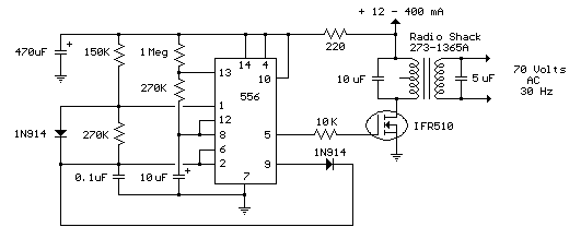
This ring generator will
ring a telephone once every 10 seconds. The interval between rings can be
lengthened or shortened by varying the value of the 1 Meg resistor. The 70
volt/ 30 Hz ring voltage is produced from the 120 volt side of a small
12.6 VAC power transformer (Radio Shack 273-1365). Both capacitors
connected across the transformer windings are non-polarized / 100 volts.
Circuit draws about 300mA from the 12 volt DC power supply during the
ringing interval.
Original scheme edited by Bill
Bowden, http://www.bowdenshobbycircuits.info
Telephone In-Use
Indicator

Original scheme edited by Bill
Bowden, http://www.bowdenshobbycircuits.info
Telephone In-Use Relay
Controller

Original scheme edited by Bill
Bowden, http://www.bowdenshobbycircuits.info
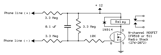
Circuit to close a relay
when any phone extension is off-hook. Voltage at the gate of the MOSFET
should be negative (1-3 V) with respect to the source when phones are
on-hook. Voltage at the gate should be positive (8-10 V) with respect to
the source (ground) when any phone extension is off-hook. A high impedance
meter is needed to measure the on-hook voltages accurately. Circuit should
draw less than 5 uA from the phone line. Relay used is a 12 V DC / 120ohm
coil, but most any small 12 V DC relay should work. Power supply
regulation should be +/- 2 V.
Telephone Audio
Interface

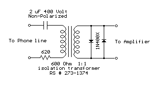 Audio
from a telephone line can be obtained using a transformer and capacitor to
isolate the line from external equipment. A non-polarized capacitor is
placed in series with the transformer line connection to prevent DC
current from flowing in the transformer winding which may prevent the line
from returning to the on-hook state. The capacitor should have a voltage
rating above the peak ring voltage of 90 volts plus the on-hook voltage of
48 volts, or 138 volts total. This was measured locally and may vary with
location, a 400 volt or more rating is recommended. Audio level from the
transformer is about 100 millivolts which can be connected to a high
impedance amplifier or tape recorder input. The 3 transistor amplifier
shown above can also be used. For overvoltage protection, two diodes are
connected across the transformer secondary to limit the audio signal to
700 millivolts peak during the ringing signal. The diodes can be most any
silicon type (1N400X / 1N4148 / 1N914 or other). The 620 ohm resistor
serves to reduce loading of the line if the output is connected to a very
low impedance. Audio
from a telephone line can be obtained using a transformer and capacitor to
isolate the line from external equipment. A non-polarized capacitor is
placed in series with the transformer line connection to prevent DC
current from flowing in the transformer winding which may prevent the line
from returning to the on-hook state. The capacitor should have a voltage
rating above the peak ring voltage of 90 volts plus the on-hook voltage of
48 volts, or 138 volts total. This was measured locally and may vary with
location, a 400 volt or more rating is recommended. Audio level from the
transformer is about 100 millivolts which can be connected to a high
impedance amplifier or tape recorder input. The 3 transistor amplifier
shown above can also be used. For overvoltage protection, two diodes are
connected across the transformer secondary to limit the audio signal to
700 millivolts peak during the ringing signal. The diodes can be most any
silicon type (1N400X / 1N4148 / 1N914 or other). The 620 ohm resistor
serves to reduce loading of the line if the output is connected to a very
low impedance.
Original scheme edited by Bill
Bowden, http://www.bowdenshobbycircuits.info
Ham radio Data Center - free schematics | 73s.eu - Free Ham Radio Social Network | Free HAM Directory | About me | Acronyms | CW | Data Sheets | Docs | Download | E-mail | HOME | Ham projects | Hobby circuits | Photo galery | PIC | QTH photos |
Sign in my guestbook | View my guestbook ]
© 2001 - YO5OFH, Csaba Gajdos
|
 The
telephone ring generator shown below generates the needed high voltage
from a simple switching mode power supply (SMPS) which employs a CMOS
Schmitt Trigger square wave oscillator, 10 mH inductor, high voltage
switching transistor (TIP47 or other high voltage, 1 amp transistor) and a
driver transistor (2N3053). The inductor should have a low DC resistance
of 1.5 ohms or less. The switching supply must have a load connected to
prevent the voltage from rising too high, so a 22K resistor is used across
the output which limits the voltage to about 120 DC with the phone ringer
disconnected and about 90 volts DC connected. The output voltage can be
adjusted by changing the value of the 150K resistor between pins 10 and 11
which will alter the oscillator frequency (frequency is around 800 Hz as
shown). The supply is gated on and off by a second Schmitt Trigger
oscillator (pins 12/13) so that the phone rings for about 2 seconds and
then the circuit idles for about a minute between rings. These times can
be adjusted with the 10K and 300K resistors connected to pin 12. The push
button shown is used to manually ring the phone. The 25Hz ringing
frequency is generated by another Schmitt Trigger oscillator (pins 1/2)
which controls the H bridge transistor output circuit. The 6 transistors
in the output stage (4 NPN, 2 PNP) should be high voltage types rated at
200 volts collector to emitter or more. The ringer will only draw around
10 mA, so the output transistors can have a low current rating but must
have a high voltage rating. I used TIP47s and small signal PNPs of unknown
numbers that I had on hand, but other types such as NTE287 (NPN) and
NTE288 (PNP) should work. Both have a 300 volt C-E rating and cost about
$0.95 from mail order houses.


 Audio
from a telephone line can be obtained using a transformer and capacitor to
isolate the line from external equipment. A non-polarized capacitor is
placed in series with the transformer line connection to prevent DC
current from flowing in the transformer winding which may prevent the line
from returning to the on-hook state. The capacitor should have a voltage
rating above the peak ring voltage of 90 volts plus the on-hook voltage of
48 volts, or 138 volts total. This was measured locally and may vary with
location, a 400 volt or more rating is recommended. Audio level from the
transformer is about 100 millivolts which can be connected to a high
impedance amplifier or tape recorder input. The 3 transistor amplifier
shown above can also be used. For overvoltage protection, two diodes are
connected across the transformer secondary to limit the audio signal to
700 millivolts peak during the ringing signal. The diodes can be most any
silicon type (1N400X / 1N4148 / 1N914 or other). The 620 ohm resistor
serves to reduce loading of the line if the output is connected to a very
low impedance.