The GPS DISCIPLINED GPSCLOCK
By Murray Greenman ZL1BPU
A simple precision GPS reference, with LCD display and clock.
Use a GPS or TV reference for incredible accuracy.
INTRODUCTION
This design is an extension of and replaces the popular
Superclock,
and uses almost exactly the same hardware. The additions are a voltage controlled TCXO
(VTXO), a GPS 1PPS reference source, and a few resistors and capacitors.
The design locks the 10MHz TCXO to the GPS reference, in just a few minutes, and
is capable of providing a low noise, accurate reference, with performance at the
level of a few parts in 109 (1e-9) or better. In addition to operating
the clock, the reference can be buffered and used to operate dividers for other
reference frequencies.

The GPSCLOCK
Dimensions: w=180mm h=150mm d=30mm
The clock and reference continue to operate when GPS is lost, and although the
reference frequency will then drift about due to small temperature effects,
it is held digitally at the current operating point until GPS returns. The clock
is essentially bullet-proof - it will be accurate to parts of a second per year,
even if GPS is occasionally or frequently lost, or power is occasionally lost.
Here is a summary of the special features of the GPSCLOCK:
- 10MHz GPS disciplined reference accurate to well within 0.1Hz at 10MHz
- Completely reliable UTC and local time clock, with hourly chime
- Battery backup with power fail indication on display and beeper
- GPS fail indication, ride-through operation with GPS lost
- Seven user-settable modes (one operating, the rest for test purposes)
- Continuous display of oscillator phase and controller output
- Serial control and telemetry - no controls to misadjust - long term phase plot on PC
- Works with 16x1, 16x2, 20x2 and 24x2 LCD displays
- High performance 16-bit maths, 12-bit PWM feedback, averaging for noise reduction
- Gain (integration time) adjustable to suit your reference

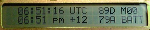
The 16 x 2 back-lit clock display
The display shown is a 16 x 2 unit. At the top left is the UTC time, in 24 hour format.
Below this is the local time, in AM/PM 12 hour format. Local time can be offset by �13 hours in one hour increments. As shown, the local time setting is +12 hours.
The information shown on the right of the 16 x 2 display is the reference phase (top) and control voltage (bottom).
When a 16 x 2 display is used, the displayed information is centred in the window.
The 24 x 2 display with extended data
The longer 20 x 2 or 24 x 2 displays allows visibility of further "engineering" information, normally hidden from the user.
This picture shows display of an earlier version of the firmware. Nothing is lost by using the more common 16 x 2 display.
The clock is simple to build - two ICs and a couple of transistors. Very likely the GPS reference
will cost more than the GPSCLOCK.
The LCD display is a standard type used everywhere, and could be recycled from a broken business phone
or appliance. A new organic LED or PLED display can also be used.
Precision time keeping is achieved through the use of a
Voltage-Controlled Temperature Compensated Crystal Oscillator (VTXO).
These can cost $30 new, but can often be found on the internet at good prices.
Just about any frequency from 9 to 15 MHz can be used, but it MUST be a voltage-controlled
type.
The clock transmits serial telemetry data, in addition to the LCD display. The serial
data can be used for time logging, or setting other clocks. The phase information
can be used for calibration or long-term tracking of the reference oscillator performance.
A special companion monitoring program has been designed for this unit.
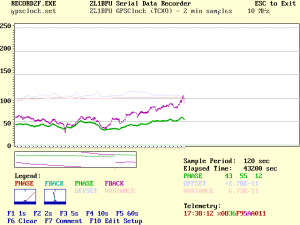
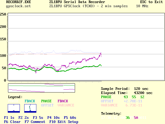
Oscillator performance monitoring with RECORD2F
Click on image to view full size.
Note the values for offset and variance calculated by the program from this 12 hour long
recording. The oscillator frequency (green trace) has not varied by more than 1e-10 in that time.
DESCRIPTION
Follow the GPSCLOCK Schematic as you read this description.
Power for the unit comes from two sources - a simple plug-pack connected to the DC socket J4, and a
backup battery, B1. The supplies are isolated from each other by diodes D3 and D4. When the plug-pack output
(nominally 10-12V DC) is higher than the battery voltage, D3 is reverse biassed, D4 conducts and the
clock operates from the AC supply. D4 also prevents reverse-voltage damage. Micro input PD2 (pin 6)
is held high by R2, R3 and D5.
When the AC supply fails, D3 conducts, D4 is reverse biassed, and the clock continues to operate from
the battery with no loss of time. However, since R2 is no longer able to keep micro input PD2 (pin 6)
high, the micro detects power failure, displays a "BATT" message and sounds the hour beeper every minute.
The battery can be a small alkaline 9V type if power failures are rare, and will last normal shelf life.
If power failures are frequent or the clock is used as a portable time source, a 6-cell 500mAH or better
NiCd or NiMH battery pack is recommended. R1 can be added to slowly charge the battery from the AC supply.
Where backlighting is used, the LED back light is powered directly from J4, so the
back light goes out when power fails, improving battery life. PLED brightness
adjustment can also
be derived from the unregulated power to reduce power-fail consumption.
Regulator U1 provides 5V with sufficient current to operate the micro controller, LCD
display and VTXO X1. The total supply current is about 10 - 15 mA. Add 40mA for
PLED display and up to 400mA for LED back lighting.
The RS232 transmit signal from the micro requires a negative voltage supply, and to keep supply current
to a minimum, this voltage is derived from the mostly idle PC transmit data line, which
is normally negative. TR1 converts to RS232 levels and transmits the serial data. Note how its collector
supply is derived from the RS232 receive line, via D1 and R28. C8 maintains the -10V supply even when
data is being received from the PC. TR2 is the RS232 receiver, with D2 catching the reverse voltage to prevent reverse bias damage. When the PC is not connected,
the RS232 interface draws no current.
J3 is the LCD connector, a standard 14 pin type. The LCD is operated in 4-bit mode to minimize the number
of micro controller pins used. R20 is the display contrast adjustment, and usually does not require adjustment
after setup (it can be internal). J1 is the programming header, a simple 2x5 pin device.
X1 is the VTXO, which needs to provide at least 1V p-p sine wave or a square wave output. The resistors
and capacitors below it to the left provide a low pass filter to remove pulse-width modulation noise
on the control signal, and also to control the gain. R23 sets the gain, while R21 is used to centre the operating
range of the micro frequency control. The two resistors R24 and R24 (values in ratio 64:1) and C2 form a very clever
and highly linear 12-bit D-A converter. The micro drives these two resistors with two independent but synchronous, weighted PWM algorithms.
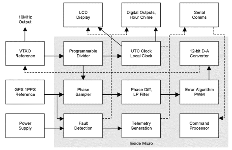
Control system block diagram
Click on image to view full size.
CONTROL TECHNIQUE
The micro controller operates in snooze mode. The main timer in the micro hardware divides down from the VTXO reference frequency, and generates an interrupt to wake up the micro
briefly every 500µsec, where the 1 kHz output is toggled and a divide by 2000 software counter stepped.
At this time the pulse width modulators controlling feedback are also cycled. One PWM uses the upper six bits of the 12-bit control value, and the other PWM uses the lower six bits. These synchronous PWM outputs are combined in a 64:1 resistor network to achieve a highly linear yet very simple 12 bit D-A converter.
Once every second the �2000 counter overflows, the 1 sec output is pulsed, UTC time is incremented, and
the output updated. When each task is done, the processor goes back to sleep. The processor is
very fast, and achieves these tasks very quickly. Thus the average current drawn by the device is
moderately low, despite the high clock speed. Time is kept by the internal clock rather than
GPS, in order to maintain time when GPS is not available. A special command makes it possible to synchronize time easily to
within 500µs of UTC.
When the GPS 1PPS tick arrives (every second of course), hardware in the micro samples the oscillator phase from the main timer within the micro. No software is involved, and sampling
resolution is 100ns. A 32 second deep sample buffer allows effective resolution to be increased to about 3ns, as phase difference is measured across 32 seconds, yet
with a new solution available every second. It is this algorithm which provides
high performance without requiring complex circuitry with a very high frequency
interpolation oscillator (the normal technique used). When no GPS is available,
no timer sample occurs and the control algorithm goes into hold mode.
The 32 second differential phase measurement is a measure of frequency offset,
with an effective resolution of 0.003Hz, and the control algorithm decrements or increments the control voltage to keep the differential phase measurement, and thus frequency offset, at zero. The rate at which corrections are added sets the system software gain. All calculations are made in 16-bit signed integer arithmetic.
Time is kept in Packed BCD format (Binary Coded Decimal), where the lower four bits
represent the units 0 - 9, and the upper four bits
represent the tens. This makes counting more tricky, but simplifies display. Every time the
UTC time is incremented, the BCD values need to be checked to ensure they follow the BCD format,
which means checking that the low nibble is <10 and the high nibble <6. The hour is checked to see
that it remains <24, and is set to zero when 23 is exceeded.
Local time is calculated by adding the local time offset, correcting the BCD, converting to 12 hour AM/PM
format, and checking the BCD again. The maths is correct with offsets as large as �13 hours. The default
offset is kept in EEPROM, along with the reference oscillator division ratio and the serial port baud rate.
COMMS PROTOCOLS
TRANSMIT (DATA)
The clock transmits time, phase and control feedback term every second, starting just after the second event. Time can be received over the serial link within
10ms of the UTC second event. The format is
HH:MM:SS %PPPPFFFF
where PPPP represents the phase of the local counter sampled by an external reference, typically
1 Hz GPS or 50 Hz TV frame pulses. The value of PPPP can be from 0000 to one less than the divisor
required from the clock reference to 2 kHz, and is expressed in 16 bit HEX. FFFF represents the feedback
control voltage, and is a 16 bit HEX number 0 - 4095, and can be interpreted approximately as millivolts.
The unit also transmits responses to some of the time setting commands.
RECEIVE (COMMANDS)
There are no front panel controls on the clock. After all, it is accurate and battery backed,
so what would need adjusting? The local time offset will need to be changed every six months
thanks to daylight saving, and at this time the clock accuracy can be checked,
for example to compensate for UTC "leap seconds". All adjustment
is achieved using the serial link to a PC. There are eleven commands:
Cmi	Command to frequency controller
Hnn	Set UTC hours to nn (BCD) hours
Mnn	Set UTC minutes to nn
Snn	Set UTC hours to nn
+ Add one to UTC seconds
- Subtract one from UTC seconds
> Increment local time offset by one hour
< Decrement local time offset by one hour
A Advance clock by 1ms
R Retard clock by 10 ms
X Synchronize to GPS second
|
The commands should be used in the order shown while setting the clock. The commands shown
in red
cause the clock to stop while they are entered, so must not be used during time-keeping.
Lower case letters are accepted and used as upper case. Invalid commands are ignored. The controller and clock can
be set with a simple ASCII terminal program, such as Windows TERMINAL, or even HYPERTERM.
The 'A' and 'R' commands are provided for rare cases where the clock must be
run ahead of or behind UTC time. For example, the serial telemetry message is
completed 20ms after the second event, and can be made to complete on the second
by advancing time 20ms.
The 'Cmi' command sets the frequency controller mode and integration time. The first number 'm' is
one of:
0 Normal (default) integral control
1 Medium gain proportional control
2 High gain (fast settling)
3 Feedback = 0 (maximum frequency)
4 Feedback = centre
5 Feedback = 4095 (minimum frequency)
6 Ramp frequency up
7 Ramp frequency down
|
The modes in red are only used during calibration. Integration time
'i' is half the number of seconds between frequency control corrections, and affects the gain (0 = maximum). The value
can be 0 - F(HEX), representing 1 to 31 seconds. Higher values give better noise performance but poorer frequency control.
USER MANUAL
A comprehensive GPSCLOCK User Manual
is available in PDF format. It includes a primer on frequency references, comparison and and calibration.
The manual gives all construction, programming, setup and calibration information.
To save this manual on your hard disc, right click on the above link and select "Save Target As ..." Read the manual thoroughly before starting to build
the unit.
SOFTWARE
The software is well tested, versatile (any reference frequency can be used), comprehensive (both for micro and PC) and is inexpensive. See the Micro Projects page for details.
Copyright � Murray Greenman 1997-2005.
All rights reserved. Contact the author before using any of this material.