Rotator Controller
An Antenna Rotator Controller
A very simple controller circuit, with fairly smart performance!
Can't afford a fully automatic computer controlled rotator, but would like more
capability from your basic rotator? Would you like a simple to use "point and shoot"
computer controlled antenna? You've come to the right place!
What it does -
- Sends the rotator to a specific heading without you needing to hold a switch down
- Allows your digital mode or logging software to control the rotator heading
- With PC software supplied, you can send the rotator to favourite headings, or a specific country
- The controller lives inside the rotator control box, and operates from its supplies
What it doesn't do -
- Control every rotator under the sun (only the inexpensive type with pot feedback)
- Operate with elevation rotors or azimuth/elevation rotors
- Provide sufficient accuracy for VHF/UHF satellite tracking
- Control more than one rotator
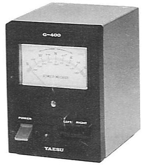 The ZL1BPU Rotator Controller has been designed as an add-on unit for the popular
Kenpro KR-400 and Yaesu G-400 rotators. The controller consists of a small
circuit board which fits inside the rotator control box (see picture).
The ZL1BPU Rotator Controller has been designed as an add-on unit for the popular
Kenpro KR-400 and Yaesu G-400 rotators. The controller consists of a small
circuit board which fits inside the rotator control box (see picture).
With this unit the rotator gains
automatic heading seeking, computer control, and even heading control by clicking on a map or
selecting a country prefix! The ZL1BPU Rotator Controller should work with any rotator with AC
motor drive and a 500 Ohm feedback pot, such as the CDR CD-44 and the HY-GAIN HAM IV.
It will also operate with both North-centred and South-centred rotators, as only the PC software
setting changes.
Computer rotator controllers tend to be expensive - however you can build this one for under $50!
The firmware supplied supports a rich specialized command set and also responds to SARTEC,
ORION and YAESU commands, making it compatable with most popular multi-function logging
and digital mode programs that feature rotor control.
The controller could also form the basis of a self-contained replacement controller, for rotators
with faulty or missing controllers. Just add the power supply circuitry shown in the
G-400/KR-400 Rotator Schematic -
all you really need is a 24V AC supply, a 6V DC supply, and a 70 - 100 uF AC motor capacitor.
 The small circuit board can be fitted inside the rotator control box, and operates from
the controller's power supply. No holes need be made in the box, and all modifications are
internal and reversible if the need arises. There are only five wires between the unit and the
existing rotator box. The serial (PC) control cable can sneak out the back panel through an
existing hole.
The small circuit board can be fitted inside the rotator control box, and operates from
the controller's power supply. No holes need be made in the box, and all modifications are
internal and reversible if the need arises. There are only five wires between the unit and the
existing rotator box. The serial (PC) control cable can sneak out the back panel through an
existing hole.
The suggested circuit board is single sided, 60mm x 60mm (without the relays),
and can be etched or engraved. See the picture to the right, which is larger than life-sized.
The board contains an inexpensive micro controller, a 5V voltage regulator, a simple transistor
RS232 interface, and two relay drive transistors to activate the rotator.
The relays are interlocked with the existing LEFT and RIGHT switches, so there is no possibility
of motor or controller damage.
The unit is given heading commands via the PC serial port, from a special program, a digital modes
or logging program with rotator control, or a simple terminal program. The commands are in the form of
hexadecimal or decimal numbers, depending on the protocol, and the controller in effect
"pushes the buttons" on the associated rotator control box until the requested
heading is reached. This means that it will go to the correct heading without the need for a
button to be held down to keep the rotator moving. It also allows for sophisticated computer
applications to control the rotator.
How it Works
Specifications
Positioning Accuracy
Accuracy is limited mostly by the host rotator and control unit. Typically 2� to 3� heading resolution and about �5�
positioning accuracy. The smallest command that will cause movement is about 5�.
A heading approached from clockwise may differ from the same heading approached from
anticlockwise by �5�. Hardly a problem with HF beamwidths of 30� or more, but not appropriate for
some VHF and UHF terrestrial and satellite systems.
The Rotator Controller uses hysteresis through the use of a window comparator
technique, to prevent hunting and poor stability, which results in the heading uncertainty specified.
The hysteresis could be reduced to improve positioning accuracy, but diminishing
returns result due to poor positioning pot supply regulation and overshoot in the motor, since these simple
rotators generally lack effective brakes. No braking control is provided.
Electrical
The Rotator Controller operates from the host controller's power supply. It requires +12V
(9 to 15V) at 10mA for the micro controller, and an additional 60mA while active (rotating).
Operation from higher supplies would be possible if the relays were changed. The Rotator Controller
includes its own +5V regulator. No heatsink is required.
The computer interface is a simple RS232 type. Idle is about -9V (derived from the PC TXD line),
and active is about +4.5V. Passive pull-down allows future multi-drop capability.
A DB9 female connector is used, and configured for DCE, allowing direct PC connection with a modem
(pin-for-pin or "mouse") cable. Communications are full duplex, 9600-N-8-1.
Only three connections are used (TXD, RXD, GND), with no handshake; thus the handshake lines
on the PC port are available for other purposes such as PTT, if the application software permits it.
Mechanical
The unit is assembled on a 60 x 60 mm single sided PCB. The relays can be added, requiring an extra
20 - 25mm in one dimension, depending on the relays used. (The KR-400 controller has 94 mm width inside,
and conveniently fits a 60 x 90 mm PCB slung from the top rails). No extra holes need be drilled in the outside
of the controller, and no non-reversible modifications need be made.
Command Protocol
Control Software
Embedded Firmware
Construction