Micro and Miscellaneous
September 2020
Introduction
Reference & Dividers
Buffers
TIC Circuit
Microcontroller Circuit
The processor used in this project is the inexpensive Arduino Nano. It has more than sufficient resources, and benefits from
a really useful USB connection, which in this case is used to provide monitoring, as well as control and parameter setting.
Parameters are kept in EEPROM, so survive power outages.
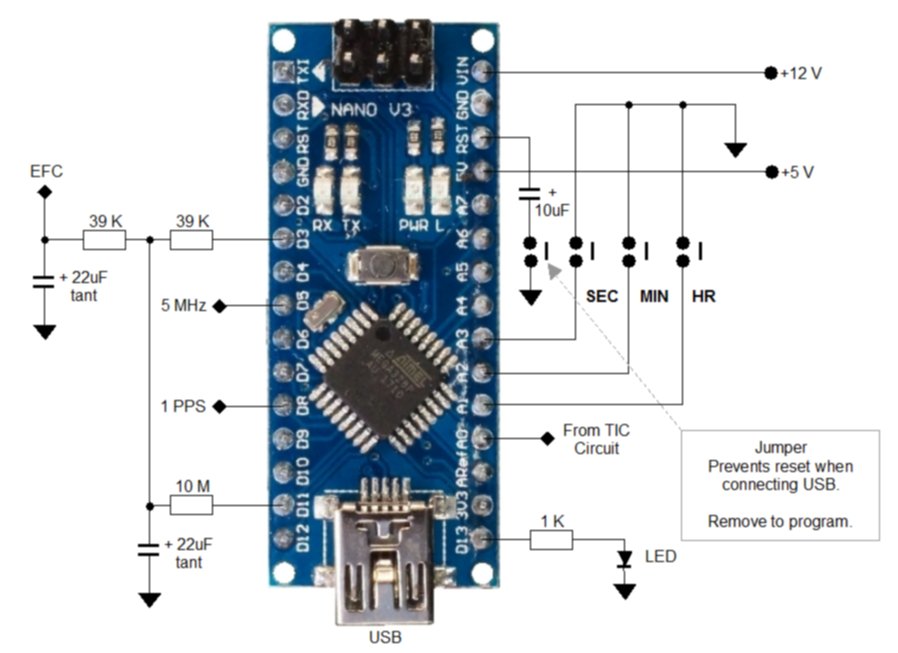
The Arduino Nano circuit.
(Click on the picture for a full-size diagram you can print).
The circuitry to the left of the micro in this drawing is the D-A converter, which uses a 16-bit PWM technique and two timers.
The most significant 8 bits are from D3, and the least significant 8 bits from D11. Because the ratio of the PWM signals is
8-bit (256), the two resistors 10 M and 39 k, must be the ratio of 256:1. For best results, trim the 39 k resistor to close to
39.0625 k, but a well chosen 39 k should be adequate.
The timers are operated by the 5 MHz clock on pin D5, while the TIC sampling and the real time clock are operated in an
interrupt process driven by the 1 PPS signal on D8.
To the right of the micro we have the three time-setting push-buttons, which you should ideally wire up with pairs
of ribbon cable wires. There is also a tricky jumper, which prevents the micro from
resetting when the USB cable is connected. However, you must remove the jumper to program the micro.
The TIC phase information arrives at the D-A input on A0, while the LED on D13 is the HOLD indicator. The LED on the
Arduino board fulfills the same function, so this LED really isn't necessary. If you include the LCD display, it is
not required at all.
Time Uncertainly Integration
While the GPS 1 PPS signal (at source) is accurate, when it is delivered from the satellite though the ionosphere, there is
some uncertainty in the timing, measured from pulse to pulse. You see this in GPS navigation, where the position is shown with an
uncertainty, which may be 5 to 50 metres.
So each individual time measurement from the TIC will also include this uncertainty. One of the most important functions of the
micro is to average out the uncertainty over thousands of pulses. It does this using a special filter between the A-D TIC
measurement and the D-A output to the OCXO. The parameters used in this software filter are adjustable in the LARS design.
The adjustments are made on an individual basis, to give optimum stability (minimum uncertainty) of the OCXO output.
Several of the so-called 'GPSDO' designs you see published are in effect 'GPS Steered', as they lack this all-important time
uncertainty integration. The result is quite poor stability. Be especially wary of designs that don't use a micro filtering
technique with adjustable parameters.
LCD Display
The LCD used is a serial type (I2C), and in the picture below you see a rear-view of the display, in order
to show the connections. This type of display is a conventional 1602 (16 x 2) display with an added 'piggy-back' board
on the back.

The serial LCD display connections, Arduino (left) and display (right).
(Click on the picture for a full-size diagram you can print).
It so happens that the pins on the micro required by the display, A4 and A5, are not
otherwise used. Not enough spare pins are available for a conventional parallel display. While the serial displays are a little slow,
the embedded code has been written carefully so this isn't obvious. Use a length of 4-way ribbon cable to connect up the display.
Power Supply
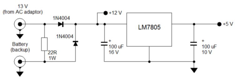
The power supply is fairly simple. Most 12 V OCXOs don't mind the actual voltage they see (± 500 mV), provided it is stable. In the circuit
below, the OCXO 12 V supply comes from the AC adaptor, via a protection diode. The 5 V regulator is also connected here.
The regulator will need a small heat sink, about 25 mm wide, with fins.
The battery charging arrangement is fairly simple. The 22 Ohm resistor limits the charge current to the 7 AH gel-cell battery
used to allow the GPSDO to ride through power failure. It should provide 24 hours backup. There will be a small change in OCXO voltage when on backup power,
and consequently a small transient in the OCXO frequency, but it should quickly re-acquire lock, and no reset will be caused,
which is the main thing to avoid.
The AC adaptor should be chosen so that its output voltage is about 13.0 V at 150 mA load. That way it can slowly top up the
battery without overcharging it. If the voltage is any higher, you could drop it using further diodes. The AC adaptor connector
is a coaxial type to suit the supply used. The battery connector is an RCA phono type. You must fit a
1 A fuse in the battery lead external to the unit.

The simple power supply arrangement.
(Click on the picture for a full-size diagram you can print).
Be very careful how the power supply is wired up. You do not want voltage changes from devices which draw significant current
(the GPS receiver, the voltage regulator and the OCXO) from affecting the stability. The GPS receiver and OCXO in particular can have
significant variation in current draw.
GPS Receiver
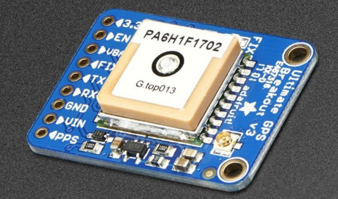 The GPS engine I used was a Garmin GPS 15xL-W, which I happened to have. It is quite a few years old, and there are now units
as good or better that are considerably cheaper. The uBlox NEO-6M or NEO-7M suggested by Lars would be quite suitable. You can
buy these and similar models by mail-order for as little as US$10, but make sure you choose one which has the ability to use an external antenna (and comes with the appropriate cable), and it also MUST have a 1 PPS (one pulse per second) output feature. Most of these
receivers are 5 V operated, but make sure, as a 3.3 V operated one will be more difficult to interface and will require another
power supply regulator.
The GPS engine I used was a Garmin GPS 15xL-W, which I happened to have. It is quite a few years old, and there are now units
as good or better that are considerably cheaper. The uBlox NEO-6M or NEO-7M suggested by Lars would be quite suitable. You can
buy these and similar models by mail-order for as little as US$10, but make sure you choose one which has the ability to use an external antenna (and comes with the appropriate cable), and it also MUST have a 1 PPS (one pulse per second) output feature. Most of these
receivers are 5 V operated, but make sure, as a 3.3 V operated one will be more difficult to interface and will require another
power supply regulator.
You will NEED to use a good outdoor GPS antenna, preferably a 'survey' or 'timing' type, which will have an optimum shaped
field of view and as a result, less timing uncertaintly. While it is possible to operate a modern GPS receiver indoors for
casual position finding, the better the antenna, and the higher it is mounted clear of obstacles, the better will be the
quality of the timing information. This will have a direct bearing on the stability of your GPSDO, and provide the highest
possible reliability. These antennas are active, and powered by the GPS receiver.
Mechanical Aspects
The prototype was built on a general purpose IC prototyping board which had ground lands between the rows of chips, and power rails
running between the chip pins. The other components were also soldered to the the board or connected by wires. The OCXO
was also securely connected at one end of the board, with the power regulator at the same end. The TIC circuit was placed at the other end of the board, with the Nano nearby. The USB connector of the Nano, and the OCXO trim control need to be on the back
edge of the board, where they can be accessed through the rear panel.
The case for the prototype was a recycled project box (200 x 150 x 65 mm), of the type sold by Jaycar and widely used in DSE
and Silicon Chip magazine projects in past years.
Firmware
If you build the design without the LCD display, you might just as well use the original LARS code:
Lars' original code, V 170801.
If however you wish to use the LCD display, have a real time clock and status information without involving a PC,
use this code:
ZL1BPU code with LCD display, V 230820b.
You will need to include the additional LiquidCrystal_I2C.h library.
Introduction
Reference & Dividers
Buffers
TIC Circuit
Copyright � M. Greenman 2020.
All rights reserved. Contact the author before using any of this material.