Just what is a GPSDO? It's a GPS Disciplined Oscillator. I guess that doesn't tell you very much! Essentially
it is a reference oscillator you can use in your shack to know exactly where 10.000,000 MHz is. Because the
reference is locked to GPS, it is inherently Accurate and Traceable.
You can read more about GPSDOs, their uses, and how they work here:
A Beginner's Guide to GPS Disciplined Oscillators, M. Greenman 2007.
More than 10 years ago, the author published a GPS Disciplined Reference (GPSDO) design based
on a small Atmel processor, with code completely written in assembler. The Time Interval Counter (TIC),
the part of the design which measures the reference and compares it with GPS,
was completely realised inside the micro, so the component count of the design was very small.
Much attention was paid to the analogue circuitry and the quality of OCXO used. While the
design has been replicated many times around the world, and the results were really gratifying,
the design proved difficult to optimise (due to code limitations), and in addition
the code, which took six months to develop, was difficult to adapt, and a headache to maintain.
ZL1BPU Simple GPSDO. The project has now been retired and is not supported.
So I thought it was time to develop a new design, and I resolved this time to use an Arduino
processor, so the code would be easier to write, and much simpler to maintain. During research
for the new GPSDO, I came across a recent design by the late Lars Walenius, which just about
completely fitted the requirements, so rather than reinvent the idea, that is the direction I took.
LARS GPSDO blog. 2007.
Unfortunately Lars died some years ago, and so there is no definitive web page or complete manual for his
design beyond what he posted on his blog. I hope that this information will correct this lack of
coherent information, and it will also offer some improvements which make the device more user-
friendly. But don't treat this information as the sole source of the design - there is much to
be learned from Lars' blog. All the credit for this design must go to Lars Walenius.
The central piece of circuitry in any GPSDO is the Time Interval Counter, or TIC. The purpose of this
is to measure the current phase of the local reference (the oscillator to be disciplined) relative
to a traceable reference, typically the 1PPS pulses from a high-quality GPS receiver.
Block Diagram of a typical GPSDO.
In the original Simple GPSDO, the TIC was achieved using the internal timers, and had a resolution
of only 100 ns. In the LARS design (as I will call it), a clever latch circuit is used. This idea was
patented many years ago. In this design the reference phase is measured in hardware, using a latch, set by the
the 1 PPS pulse rising edge, and cleared by the next reference edge, within one microsecond.
The resulting pulse, 0 to 1 µs long, is integrated on a small capacitor and immediately read by the micro-controller.
This method has a resolution of just 1 ns.

The LARS TIC (from original documentation)
My version follows the LARS TIC circuity exactly, and the rest of the design is followed with some adaptation
due to what parts were available. The prototype was built during Covid19 Level 3 Lock-Down, so there was no
opportunity to purchase parts. By all means use the original LARS components if you can.
No changes have been made to the functionality of the code, but some significant additions have been
made, which considerably improve the user-friendliness of the unit.
LCD Display
The original design used a computer link to monitor performance. This has been retained. But in order to allow
monitoring of the ongoing performance of the unit, without the need of a computer connection, a serial LCD display was added.
A serial (I2C) display was necessary as not many spare pins were available on the micro,
not enough for a parallel display, and by sheer coincidence the I2C pins were free.
Having an LCD display allows the OCXO control voltage (the EFC) to be monitored continuously, along with
the lock status, and of course this means that you don't need to have a computer connected all the time.
UTC Clock
Well, when you have a display available, and perfect GPS timing, why not display a clock? The clock is
set manually, not by reading the NMEA data from the GPS receiver. This would have necessitated a far
bigger micro (more code space) than the Arduino Nano selected. But setting the time is easy, as all
you do is connect the NMEA output from the GPS receiver (via a socket on the back panel) to a GPS
monitoring program on the PC for a few minutes while you set the clock.
I had to sacrifice the temperature measurement capability (which used the pins used by the clock
setting switches), but if you later wish to add temperature measurement, you can always add
an I2C temperature chip.
The added GPSDO display.
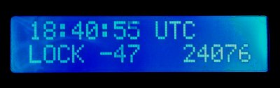
Status Indication
There are four status indications: 'WARM', SEEK', 'LOCK' and 'HOLD". The number in the middle of the lower line is the accumulated TIC offset, and on the right the EFC control voltage (range 0 to 65535).
Minor Additions
I also added a 1 PPS LED on the panel to act as GPS fix indication (the LED does not flash if there
is no fix), and three BNC sockets, for 10 MHz, 5 MHz and 1 MHz outputs. The back-lit LCD display serves
as the power indicator.
The rear panel has sockets for 12 V power, battery backup (I included a simple charger), the three
clock-setting buttons, a socket for 1 PPS output, the GPS receiver NMEA data output and antenna input,
the USB connector, and a hole which allows access to the OCXO trim pot. The unit does not at present
detect or report when it has lost AC power.

A front view of the working GPSDO.
Reference & Dividers
Buffers
TIC Circuit
Micro & Misc.
Copyright � M. Greenman 1997-2020.
All rights reserved. Contact the author before using any of this material.