Adapting the
FE-5650A or FE-5680A

Rubidium Synthesizer


Introduction

The Frequency Electronics Inc FE-5650A and FE-5680A Rubidium references are natty little units small enough to hold in your hand, and yet not only contain a high stability Rubidium Frequency Standard, they also potentially contain a 0 to 20 MHz Direct Digital Synthesizer! One of these units can serve as a useful shack reference, and because it can be remote controlled to any frequency within its operating range, it also makes the framework of an excellent synthesized signal generator with impeccable accuracy and stability. With the right software (see below) it can even become a useful QRP LF/MF/HF Exciter as well.
           
The FE-5650A (left) and FE-5680A (right)
  Manufacturer's Data Sheet
  PC Control for FE-5650A/FE-5680A
This project specifically addresses the Opt 58 version of these products, which generate only a 1pps (one pulse per second) reference (no HF sine wave output), and so have little use for other applications without modification. This also means that the units are available from internet sources at attractive prices.

Originally intended for telecoms applications, the FE-5650A Opt 58 unit has been available for some years through the surplus market. The equivalent FE-5680A version is in a more convenient package, and is of more recent manufacture. The opt 58 versions (the most widely available) do not have the RF connectors shown in the pictures above, and this is what uniquely identifies them. The FE-5650A Opt 58 has only a tiny PCB connector (not the one in the photo), and the FE-5680a a DB9M type as shown, but no BNC connector. Internally the 5650A and 5680A models are almost identical, just packaged differently. The main difference is in power supply requirements.

Without modification the units have just one output - 1pps (1 Hz). There is a simple modification to extract 8388.608 kHz, which is of course 223 Hz, and this frequency is used, through binary division, to generate the 1pps output. The 8388.608 kHz output is generated by a 32-bit Direct Digital Synthesizer chip (AD9830). This output can be steered to any other frequency within the operating range, by interacting with the controlling microcontroller, with three provisos:

  1. The unit has a peaked filter at the synthesizer output, and so the level at other frequencies varies wildly. This can be corrected with minor modifications.
  2. When operating at any other frequency than 8388.608kHz, the 1pps output is of course incorrect.
  3. The synthesizer operating frequency can be set to within �5 mHz (milliHertz) of the requested frequency,
        - but ONLY if the calculations, on which the command sent to it is based, correctly use 32-bit maths.

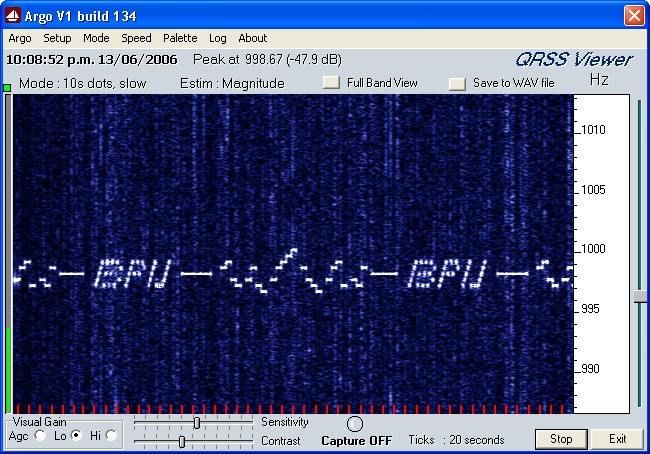
Frequency response, before and after modification

Modifications

To make the unit useful for Amateur applications, three essential modifications must be made:
  1. The serial control connections must be brought out to a suitable connector for computer control.
  2. Some changes must be made to the internal filters to improve the low frequency response.
  3. A new RF output connection must be added.
Since the modifications are covered adequately elsewhere (see links below), they will not be covered here. Unfortunately there is no schematic available for these units, so the modifications have been devised through guesswork, native cunning, and an understanding of the Analog Devices DDS chip.

Don Latham and Bill Houlne       DD1US Modifications      Notes by Mark Sims      More Notes by Mark Sims (re buffer mods)

Synthesizer Maths

The DDS chip operates from the nominal ~50.255 MHz reference derived from the physics package. The exact frequency varies slightly from unit to unit, and affects the calibration of commanded frequencies. In the original application, the synthesizer was simply given a 32-bit value which resulted in exactly 8388608Hz output. The unit can at any time be recalibrated by changing this stored value, or changing the value in any control software. The fundamental mathematical algorithms used are:

RESOLUTION = REFERENCE / 232 (Hz)
(where REFERENCE is the ~50MHz value in Hz given by the 'S' command)

COMMAND = REQUIRED_OPERATING_FREQUENCY (Hz) / RESOLUTION
(Command must then be converted to 32-bit HEX, 8 characters)

Note: The calculations must use high precision - all decimal places of REFERENCE and RESOLUTION values must be used in calculations, or the results will be inaccurate. The Windows calculator is capable of these calculations in scientific mode. In order to stay within the 32-bit capability of the calculator, always perform the calculations in two steps, and always divide before multiplying. For example, to determine a value for COMMAND, don't multiply REQUIRED_OPERATING_FREQUENCY by 232 and then divide by REFERENCE, as this combined calculation requires a 64-bit calculator!

Operating Commands

Serial communications to the FE-5650A/FE-5680A operate at 9600 bps (9600-N-8-1, Half Duplex). Signal levels and polarities follow RS232. Set your PC application to 9600-N-8-1. If using a 'terminal' application, set ECHO ON and set the incoming direction to interpret CR as CR+LF. Three serial commands are known:
S STATUS
The command S<CR> invokes a response giving the calibrated ~50MHz reference frequency from the physics package (clock reference to the DDS), and the operating frequency specified as a 32-bit HEX number. The actual operating frequency can be determined by converting this HEX number to decimal, multiplying it by the ~50Mhz frequency given, and dividing the result by 232.

The response is in the format:

R=50255057.012932Hz F=2ABB504000000000
OK
The purpose of the last eight hex characters is unknown, and they are always zero.

F FREQUENCY
This command sets the operating frequency. The command parameter is in 8-charater HEX. Divide the frequency you want by 232, then multiply the result by the ~50MHz frequency given by the STATUS command (use full accuracy with all decimal places, and a 32-bit or better calculator). Convert the result to HEX and use all 8 'hexits' (HEX 'digits'), padding with leading zeros as necessary. For example,
F=2ABB5040<CR>
will set the frequency to 8388608Hz. The step resolution is exactly the ~50MHz frequency divided by 232, or about 0.01Hz.

E EDIT
This command stores the default (power-up) operating frequency. The command E<CR> causes the current frequency to be stored for use at power-up. There is no response from the unit.

It's probably not a good idea to play with this command too often, as it writes to EEPROM which may have a limited write life. In addition, changing this value affects calibration, necessitating a change to the RUBY4 software setup; when using the unit with a PC and self-calibrating RUBY4 software, there is of course no need for continued use of the 'E' command for calibration.

Note: Other than by trimming the 'C-Field' pot inside the unit, there's no way to ensure that the unit is closer to the requested frequency than half the resolution (~0.005Hz). If you do trim the C-Field pot, it will however only hold good for the one frequency. This behavour is quite unlike that of a PLL synthesizer.

Operating Software

No commercial software is known to exist for this unit. Two programs are currently available from ZL1BPU. The programs are essentially similar, in that they set the FE-5650A/FE-5680A operating frequency to within �0.005 Hz using 32-bit maths, and also allow the output to be turned off (well, set to an impossibly low frequency!). One program also allows the unit to operate as a slow-speed beacon or stepped generator, generating any pattern of up to 16 equally spaced frequencies, at any rate from 1Hz downwards in 1Hz steps.

RUBY4
This is a text-mode DOS executable program which should operate in a DOS box with every flavour of Windows.
It will also operate on the oldest slowest PCs, as well as the HP200LX palmtop. There are just three commmands:
- Enter the operating frequency in Hz (to two decimal places) and press ENTER. The synthesizer will go where you send it within about 200ms.
- If you preface the command with '#', and use exactly valid eight HEX characters, it will also recognise native DDS frequency values.
- Enter '0' as the frequency to turn the generator output off.
- Press ESC to exit the program.

RUBY4 uses a setup file (RUBY.SET) to define the serial port, the calibration frequency and the calibration command value. By playing with this last value, you can effectively over-ride or correct the internal calibration of the FE-5650A/FE-5680A synthesizer without making any permanent changes. The format of the RUBY.SET file is:

COM PORT (1 or 2)
8388608 (Default frequency in Hz for which calibration applies)
CALIBRATION VALUE (HEX command which results in the default frequency e.g. 2ABB4D86)
The last value is usually (but need not be) the one given by the S STATUS command. If you change the default frequency or recalibrate the unit, these values change. The software uses these values to work out the frequency resolution, and thus calculate your frequency commands accurately. RUBY4 is available for free download from the links on this page.

RUBYP2
This is also a text-mode DOS executable program which should operate in a DOS box with every flavour of Windows, and has similar appearance and commands to RUBY4. It also uses the same setup file. However, this program also has a built-in beacon and pattern generator! It allows the unit to be operated as a simple sweep generator or as an LF/MF/HF Exciter, for example to use for test transmissions or as a beacon.

When you enter the command '3', you are prompted for the the name (without suffix) of a script file (must be suffix '.scp'). This text file contains the following parameters:

- Default duration of each frequency in seconds (must be integer)
- Frequency separation of generated frequencies in pattern (resolution ~0.01Hz)
- The pattern - a single line of HEX character commands specifying which frequency is sent in each interval.

The frequencies are generated sequentially, one at a time, and are created with phase coherence for minimum keying noise. The nominal frequency (see later) is that specified in the last frequency command, while other frequencies are this value plus the separation times the value of the character in the script - 8, 0-9 and A-F. In otherwords a value of 8 generates the nominal frequency.

The file format must be as follows:

duration
separation
pattern1 pattern2 ...etc
any text comment...
The frequency steps are either positive or negative, about the nominal specified frequency, with frequency increasing as the number increases (that is, if the separation is positive; separation can be negative for LSB use, when the frequency decreases as the command character increases). The nominal operating frequency must first be set before starting the script using the frequency command, and is the frequency generated for step '8'. See the example below:

The script pattern can be any length up to 256 characters, which must be on one line. Just about any Morse, carrier, text or graphics image can be created. Invalid characters are ignored, so you can place spaces in the script to make it easy to follow. Since subsequent lines in the script are not read, you can also add a text comment. Once the end of the pattern is reached, the pattern starts again with no delay.

Three further letter commands are recognised in the scripts:

Sn SPEED
'n' is a duration multiplier for frequency elements, allowing the speed to be changed during the message.
The multiplier is n+1. The default multiplier is 1 (n=0). 'n' is 0-9 or A-F and operates on the element period set in the
script file, so use the script file to set the duration of the shortest elements in the script. Individual elements can
also be stretched by simply repeating them - there will be no glitches.
Q QUIT
Exits the pattern after one iteration (can only be the last character in the script, as all following are ignored).
X OFF
Generator off for one element duration. There is no way to prevent keying sidebands when using this command,
since the generator starts and stops instantaneously, although the results are fairly good!


Click on image for larger view

The above screen-shot shows the unit transmitting three modes on 80m (a nominal frequency of 3712500Hz), received using I2PHD's ARGO in '10-sec slow' mode. The three modes are: carrier (nominal frequency), Sequential MT-Hell above and below the nominal frequency (the letters 'BPU') and 'CASTLE' mode (the pattern of dots in the centre, reading 'ZL1BPU' in Morse). Note that 'CASTLE' mode straddles but does not transmit the nominal frequency. Click on the above image and see if you can decode the Morse - it's easy! The speed was slowed by a factor of 3 at the start to send the carrier and CASTLE segments, then restored to 3 sec for the MT-HELL. The script for this pattern was:

3
0.5
S2888888XX9A76X7965X79ABCX9765X79A6X769X88888XXS06789A68A68A68A79XX6789A8XA8XA9XX6789A6X6X6789AXXXX
How about a simpler example! To generate repeated positive ramp with 16 steps, moving up 0.5Hz every second, use the following script:
1
0.5
0123456789ABCDEF
Another example, to generate QRSS3 DFSK Morse (3 seconds per element) sending 'ZL1BPU --------' just once. In this example, the generator is turned off for 'key up', while 1Hz up is used for dot and 3Hz up used for dash. The pattern is distinctive and easy to read:
3
1
X9X97X7XX797X7XX79X9X9X9XX97X7X7XX79X97XX7X79XX88888888XXXQ

In the final example, a 60 second carrier is followed by 'BPU' in QRSS10, ASK keyed - all on the same (nominal) frequency:

10
1
888888X888X8X8X8XXX8X888X888X8XXX8X8X888XXX

The RUBYP2 software is not free. The usual charges apply. See Project TF.5. The program comes with example scripts.

  Manufacturer's Data Sheet
  PC Control for FE-5650A/FE-5680A
  RUBY4 Help Information

Copyright � Murray Greenman 1997-2009. All rights reserved. Contact the author before using any of this material.