High Altitude Balloon Flights Carrying HF Radio Telemetry
A miniature HF telemetry transmitter flying under a 'super pressure' party balloon.
After tracking recent Picospace balloon flights I got 'the bug' to fly some more of my own balloons. This time the aim is to reduce payload weight to gain extra altitude while still flying under a 36" diameter party balloon at a minimal cost. The following flights use lightweight 'tracker/telemetry' transmitters built following the concept of the QRP-Labs U3S transmitter, and running a modified version of QRP-Labs U3S firmware.
Link to past flights BB01 to BB05 Link to flight BB06
Link to flight BB08
Link to flight BB09
Link to flight BB10
Link to flight BB06
Link to flight BB08
Link to flight BB09
Link to flight BB10

Balloon flight BB07 - currently MIA!
BB07 launched at 21:30 UTC on 02 April 2020
07 April 00:00 UTC ... not a peep for 4 days. BB08 will go up when conditions are suitable (possibly on 10 April)
04 April 04:00 UTC ... nothing heard (seen) from BB07 all day. What ever failed as it reached the float altitude yesterday appears to be terminal. We'll keep looking for a few days, but in the mean time the tracker transmitter board for BB08 is being tested on the workbench!
03 April 06:00 UTC ... nothing heard (seen) from BB07 all afternoon. By now BB07 will certainly be near sunset and there won't be any chance for a signal until an hour or so after sunrise in the morning.
03 April 00:12 UTC ... transmissions stopped coming. During the last transmissions, one of the WSPR signals had some 'noise' on it and perhaps this was a solder joint or component beginning to fail? Monitoring ...
02 April 21:30 UTC ... slightly more breeze than I'd have liked for the launch, but BB07 got away safely and is sending back reports. The following things are different on this flight:
Balloon - 36" silver Qualatex (was a 90cm 'Chinese clear' balloon on BB06)
Tracker transmitter - cut-off PC board (full board on BB06)
GPS - a GPS reset system on test for the first time (details below)
Solar - 6 cells and no regulator (4 cells and a boost regulator on BB06)
BB07 over-view:
Balloon: a 36" dia Qualatex silver balloon with enough hydrogen gas to provide 3.3 grams of free lift over the total payload weight
Payload: a QRP-Labs U3S based transmitter sending 20mW of WSPR mode tracking and JT9 mode information on the 20m band
Antenna: a halfwave dipole (0.1mm dia wire) supported on 4 pound fishing braid, with the transmitter suspended at the feed point
Total payload weight (transmitter + solar cells + antenna): 1.47 + 2.63 + 0.93 = 5.03 grams
The tracker transmitter is 'flying naked' ... there is no insulation or other coating on the PCB
Anticipated 'float altitude': 9,900m (subject to external conditions like temperature and air pressure)
BB07 hardware compliment:
GPS - ATGM336H with an experimental reset system
Processor - ATmega328P-AU
Processor clock - 8MHz
Synthesiser - Si5351a
Synth reference - 27MHz TCXO
Solar cells - six 39mm x 19mm 0.12W solar cells in series producing about 3.4V in bright sunshine
Voltage regulator - none
Transmitter frequency:
The WSPR and JT9 signals are received with a receiver tuned to the standard 20m band WSPR 'dial frequency' of 14.095600 MHz. The WSPR appears on the waterfall in the upper half of the WSPR passband (at about 1565Hz), and the JT9 appears about 130Hz higher (see the screen shot in the pictures below). There is also a "reset tone" sent as part of the GPS reset system implemented for the first time on this flight to try and overcome the failure of the GPS module to start properly on some days.
Transmitter schedule:
MinuteTransmission
:x2CW reset indication ("000" followed by an "E" - see Experimental GPS Reset System information below)
:x4Standard WSPR mode
:x6WSPR telemetry (channel 02)
:x8JT9 plain text using message 00 with QRP-Labs U3S tags #CS #M6 (Call sign, 6 character Maidenhead locator)
:x9JT9 plain text using message 01 with QRP-Labs U3S tags #A0 #A3 #AT (not used, not used, Altitude)
:x0JT9 plain text using message 02 with QRP-Labs U3S tags #GS #GC (Speed in knots, Course in degrees true)
#A0 and #A3 (temp and volts) are not used on BB07. #AT, #GS and #GC are from the GPS output strings.
Experimental GPS reset system:
This uses the 'band' feature of the U3S firmware to create a reset pulse. The 'Band 0' output pin of the ATmega328P-AU processor is connected to the GPS module's reset pin, and is activated by the relevant firmware programming as follows:
'Frame Start' parameter: 10 02
'Mode' parameters:
Mode 0Band = 2Frequency = 014,097,300Mode = CWMessage no. = 03Aux = 0
Mode 1Band = 0Frequency = 014,097,300Mode = CWMessage no. = 04Aux = 0
Mode 2Band = 2Frequency = 014,097,166Mode = WSPRPower = 13Aux = 0
Mode 3Band = 2Frequency = 014.097,166Mode = WSPR (telemetry)Power = 06 (telemetry channel 02)Aux = 0
Mode 4Band = 2Frequency = 014,097,300Mode = JT9-1Message no. = 00Aux = 0
Mode 5Band = 2Frequency = 014,097,300Mode = JT9-1Message no. = 01Aux = 0
Mode 6Band = 2Frequency = 014,097,300Mode = JT9-1Message no. = 02Aux = 0
'Messages' parameter:
Message 00QPR-Labs tags #CS and #M6
Message 01QPR-Labs tags #A0 and #A3 and #AT
Message 02QPR-Labs tags #GS and #GC
Message 03{space}{space}{space}000{space}(the spaces around the zeros are just for visual effect on the waterfall)
Message 04E
These are programmed into the firmware as#CS #M6[]#A0 #A3 #AT[]#GS #GC[] 000 []E
The effect of this programming is as follows:
MinuteAction
:x2GPS reset pin held high, 15 'dahs' are sent to mark the waterfall signifying the start of the reset process
:x2 + a few secondsGPS rest pin briefly goes low while 1 'dot' is sent, the GPS module resets, the reset pin returns to high
:x4 onwardsWSPR and JT9 transmissions on schedule as above with the reset line held high until the next :x2 minute
Decoding and tracking:
The WSPR telemetry capture, decoding and forwarding is done by a version of Aaron M7REG's python script (forked from SM3ULC) with further modifications by Andy VK3YT and myself. Thanks also to Jim N2NXZ for the set-up tips that saved a lot of potential grief.
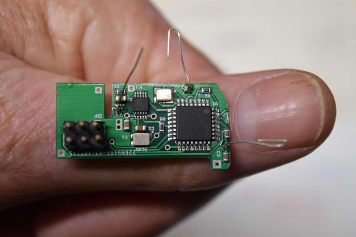
BB07 uses a PCB gerber file from SA6BSS, but with the GPS mounting area cut off to save weight. The GPS module is glued under the board and the connections to it are made in 'dead bug' style with 0.15mm wires. The 6-pin ISP header at the left hand end is cut off prior to flight
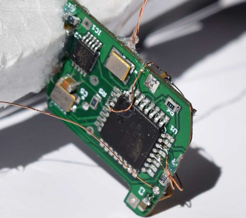
The processor side of the modified board. The programming header has been cut off ... no going back!
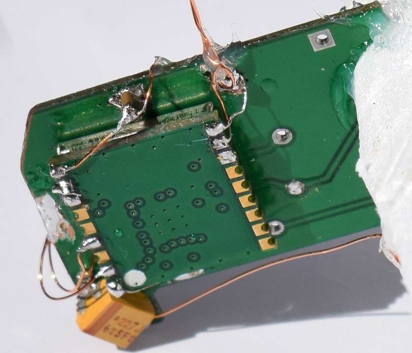
The GPS side of the modified board
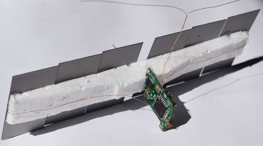
An overall view of the solar cells and transmitter
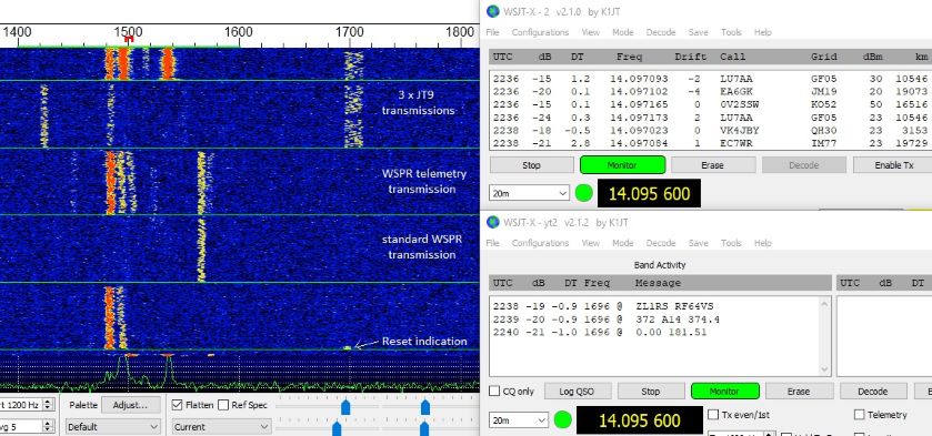
A screen shot of the waterfall showing the Reset + WSPR + JT9 trails, and the associated decodes
More BBxx series balloon flights are coming ...
|