Between 06 UTC 25 May 2016 and 04:04 UTC 05 June 2016 there was a UTC time update problem. This was traced to a bug in the PICAXE power saving program that was not apparent during weeks of testing and the first two weeks at sea. During that 2 weeks the Floater was transmitting once per hour, but the timing was 10 seconds early ... however, thanks to an idea by Remco PA3FYM and implementation by Wolf DL4YHF, a version of Wolf's fine rsNTP program was developed with a "Floater Time Offset"!
Since 04:04 UTC 05 June 2016 the Floater transmission timing has reverted back to UTC. If you are using rsNTP with the special 10 second offset, de-select this in the 'Options'.
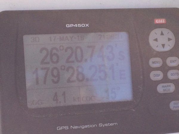
14:00 UTC 26 July 2016 - The Ocean Floater passed close by the Ono-i-Lau group of islands of Fiji
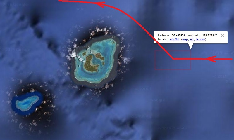
The larger island near AG09RI is Ono Levu in the Ono-i-Lau group south of Fiji. The Floater had been travelling steadily west but the ocean current sweeping around the island turned the Floater northwards.
Latest news - 09 April 2017 - Tropical Cyclone "Cook"
On 08 April a weak tropical cyclone (hurricane) developed over Vanuatu at about 500km (300 miles) NE of the Floater. This storm was updated to Cat 2 on 09 April and is travelling SSW towards New Caledonia. Depending on the actual track, by 10 April it could be in the vacinity of the Floater and strengthened to Cat 3 with winds up to 85 knots (157 kmph - 97 mph - 43 m/s).
update 12 April 2018: Cyclone Cook turned SE and had little effect on the Ocean Floater.
The Floater's drift track near the reefs at the northern end of New Caledonia from March to 25 April 2017.
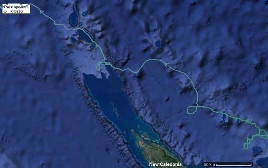 The Floater actually crossed several submerged reefs and passed through three lagoons before emerging into the open ocean again.
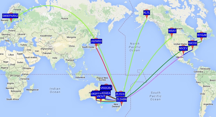
An example of WSPR spots over a 24 hour period while under pre-launch test at RF64VT
An example of JT9 telemetry decodes while on test:
2016 Apr 28
0626 22 -1.0 1728 @ ZL1SIX RF64VT
0627 21 -1.2 1728 @ BAT425 TMP196
0726 22 -1.0 1728 @ ZL1SIX RF64VT
0727 20 -1.0 1728 @ BAT424 TMP191
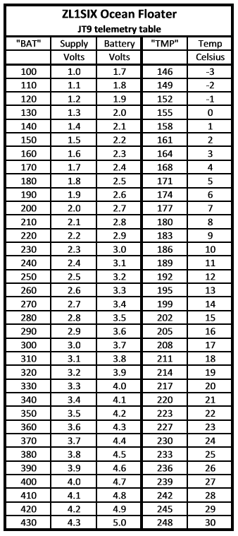
The JT9 telemetry figure BATxxx divided by 100 gives the 'supply' voltage. The battery voltage is 0.7V higher due to the protection diodes in the battery pack. The second telemetry figure TMPxxx minus 155 then divided by 3.12 gives the internal temperature e.g. (203 - 155)/3.12 = 15.4 degrees Celsius. A convenient 'quick lookup table' is provided below:

Project build history:
July to September 2015 ... under development and construction (aka "making it up as we go along"!)
A mish-mash of ideas ... PVC drain pipe buoy with "anti-bobbing" float, fishing rod + tapered SS whip antenna, GPS and high efficiency inverter power supplies, QRP-Labs U3S items, PICAXE power management controller to extend battery life, battery bank of 18 alkaline D-cells in 3-series x 6-parallel configuration for power supply and as part of the buoy stability ballast. The anticipated life from the 18 x D-cell alkaline battery bank is difficult to estimate due to the inverters drawing more current as the battery voltage declines, but between 12 and 14 months is expected.
A solar charged lithium battery power system was tested but discarded due to the panel size required and potentially poor 'survivability', both due to salt build up on the panels (further reseach has shown that assumtion to be completely wrong), and being on the ocean during a storm as being like in a washing machine! The small panels tested gave very poor solar charge performance under cloudy skys.
Theory of operation:
Continuously running ...
A low drain, high efficiency 3.3V inverter/regulator and PICAXE 08M2+ at 1.1mA current consumption to provide power management of the GPS and TX to extend the battery life. 3.3V is also supplied continuously to the GPS 'backup' pin to retain data for a fast GPS 'warm' start (typically less than 15 seconds if there are sufficient satellites in view).
at about 2 mins 20 seconds into the hour long cycle ...
- a PICAXE timer loop turns on the GPS to get the UTC time and position update
- another timer loop turns on the QRP-Labs CPU and Si5351A synthesiser kit to 'warm up'
at 4 minutes ...
- another timer loop turns on the 5V inverter/regulator that runs the PA stage
- a standard WSPR transmission is sent on the 30m band with 4 character grid locator from the GPS
- the PICAXE timer loops are syncronised to UTC by the 'band 2' signal from ATmega328 pin 16
- the GPS is switched off to save battery consumption
at 6 minutes ...
- JT9 transmission on the 30m band of callsign and 6 character Maidenhead locator
at 7 minutes ...
- JT9 transmission on the 30m band of battery voltage (BATnnn) and temperature (TMPnnn) telemetry
- at 7 minutes and 40 seconds the GPS is switched back on
at 8 minutes ...
- Calibration
- at 8 minutes 20 secs the PICAXE turns off the GPS/CPU/synth/PA for 54 mins to save power
Battery pack ...
This consists of 3 alkaline D-cells connected in series to give a nominal 4.5V supply, and 6 sets in parallel to increase the battery bank capacity. There are series diodes from each parallel battery string to isolate them in case one battery develops a fault. The series diodes drop the effective battery voltage by 0.7V to become a nominal 3.8V supply.
Alkaline D-cell battery capacity at a low discharge rate is 20A/hr per string of cells, so 6 strings in parallel gives 120A/hr total capacity. The average power consumption of the transmitter is just 11mA/hr but the drain on the batteries increases as the 'supply' voltage reduces due to the operation of the 3.3V and 5V regulators when in boost mode. This makes the expected life difficult to calculate accurately and battery capacity is also dependent on temperature (higher when warm).
An A-D input on the PICAXE controller is monitoring the 'supply' voltage and the PICAXE firmware tests the voltage at the beginning of each hour long cycle. It is set to shut the system down when the 'supply' voltage reaches 1.2V to prevent eroneous operation (the boost regulator minimum input voltage spec is 0.8V). A 1.2V 'supply' voltage via the isolation diodes is 1.9V at the batteries, or 0.63V per cell which is just below their nominal 'flat battery' voltage specification.
Special note ...
The QRP-Labs U3S and QRP-Labs Si5351A synthesizer kit have been modified to work at 3.3V. The ATmega328 is out of spec (overclocked) while using the 20MHz clock crystal at 3.3volts, but somehow it still runs reliably (so far!) The brown-out 'fuse' setting in the ATmega328 had to be altered to suit the lower operating voltage. The QRP-Labs synthesizer kit has had the LM317 regulator and level converter FETs removed. The unused 'clock output' tabs on the synth PCB have also been cut off to make the board smaller.
Photos:
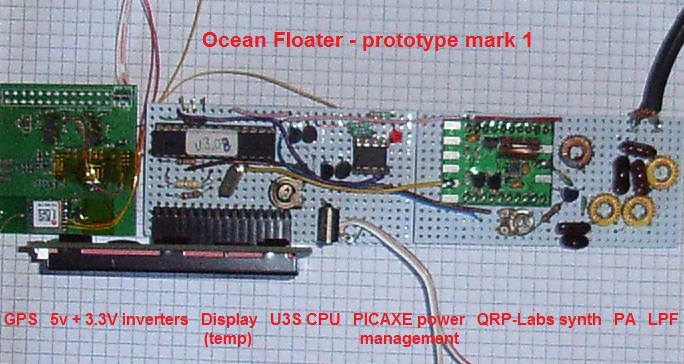
Prototype 1 - GPS locked QRP-Labs U3S based 200mW WSPR/JT9 transmitter (30m band)
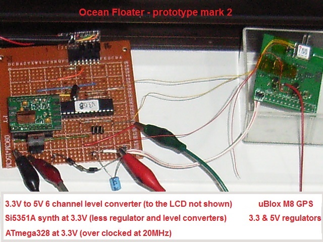
Prototype 2 - modified QRP-Labs U3S CPU/Synthesiser at 3.3V making a significant Watt-hr power saving to extend the battery life. PA stage and PICAXE controller to be added
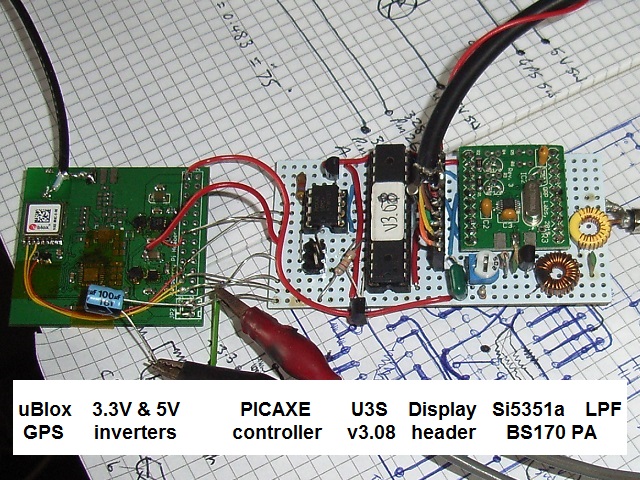
Final version before mounting on its copper chassis support and fixing to the fishing rod reel seat. Built with the PICAXE power management controller, TMP36 temperature sensor (the transistor-like device sticking out the side of the board), BS-170 FET PA and a 3-pole LPF. The measured power output on my spectrum analyser is +21dBm (~125mW), and the harmonics are better than 35dB down (less than 0.05mW)
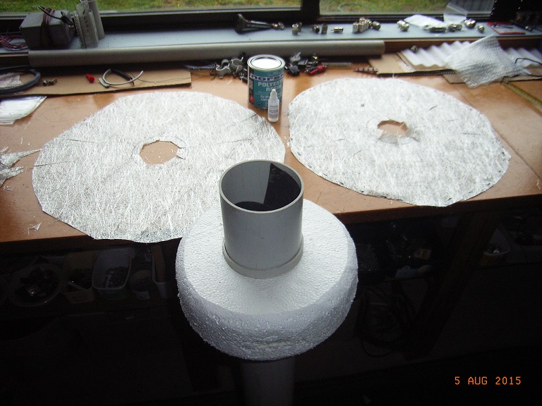
Polystyrene 'anti-bobbing' float to be coated with chopped mat and resin to waterproof and strenghten. The resin reacted badly with the polystyrene, so construction adhesive was used as a 'resin' to hold the chopped mat in place (see below)
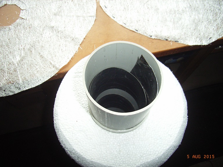
A spiral of sheet metal inside the PVC buoy tube as a ground. This provides about 1500pF of capacitive 'connection' to the surrounding sea water 'earth' thereby eliminating any underwater penatrations in the buoy housing that might leak
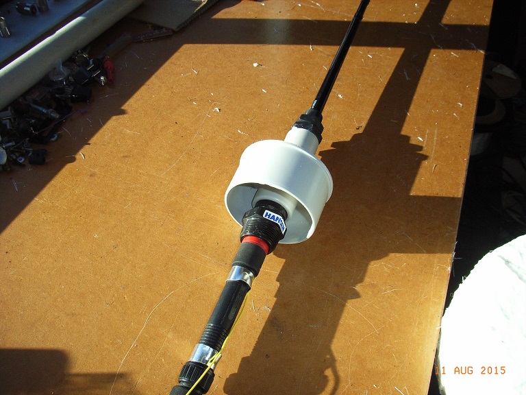
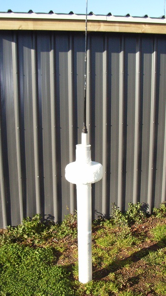
Plumbing fittings for the buoy top cap and 'fishing rod' antenna. A length of wire inside the fishing rod is connected to a 1.2m long SS whip out the top giving a total antenna length of about 2.4m. To be fed via a base loading network (L-match)
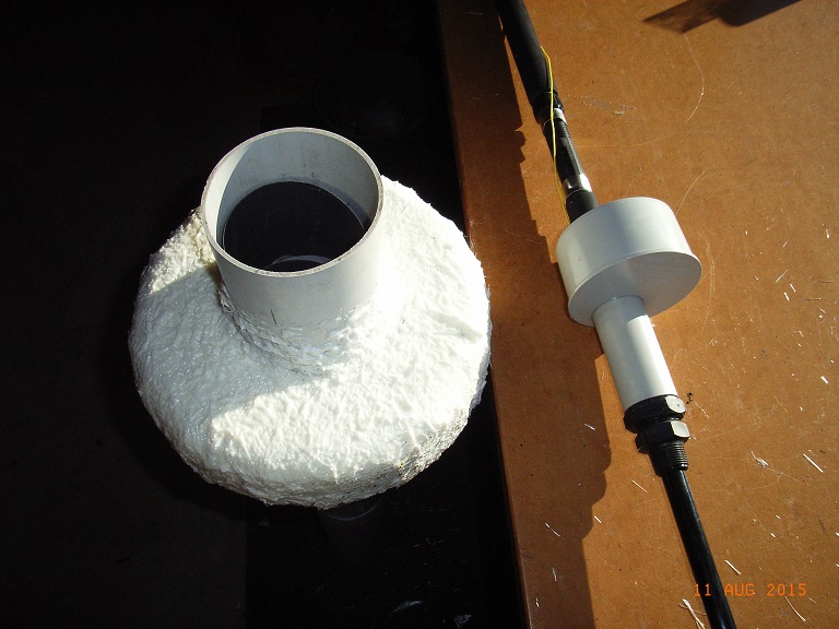
'Anti-bobbing' float covered with chopped mat and polyester construction adhesive, to be re-coated in resin for greater strength and protection
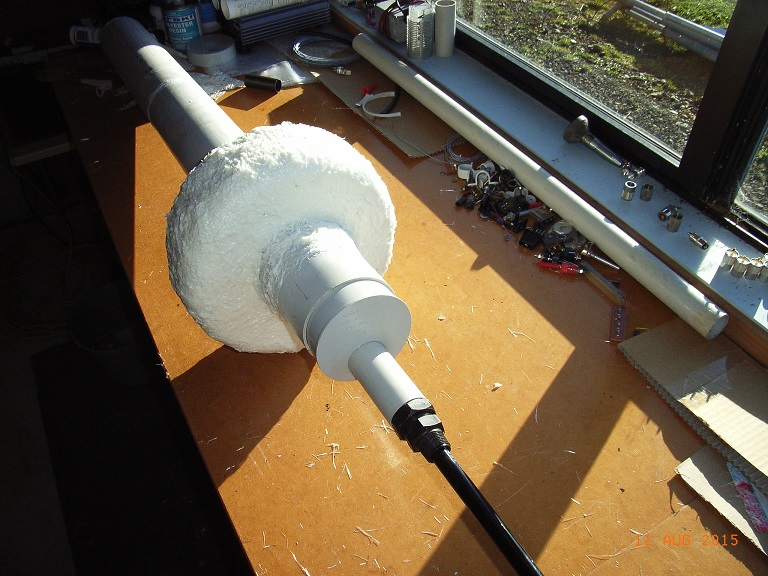
Partially inserted top cap and antenna to check the fit. The float has since been covered with 2 coats of 2-pot resin
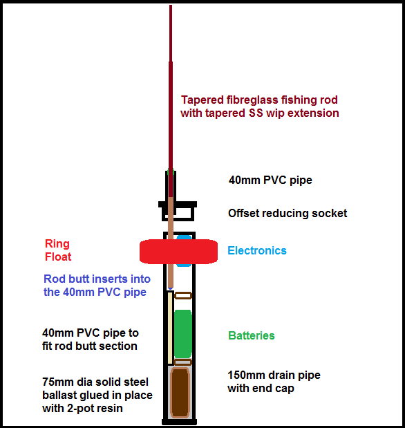
Internal layout of the buoy
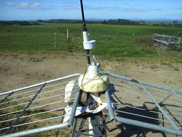
Testing with the L-match network at the base. The galvanised steel farm gates are the ground plane!
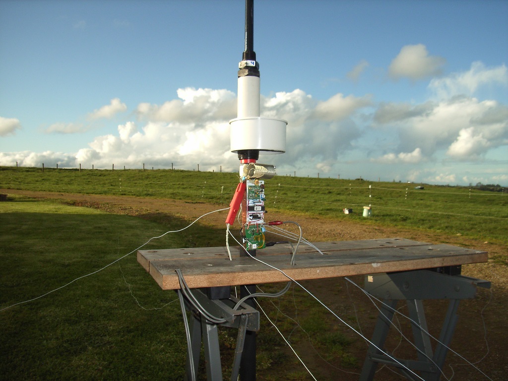
Final TX and L-match configuration being tested against 8 wire radials as a ground plane.
Closer shot of the TX and L-match.
Battery pack and floater body tube.
Many thanks to the following who have contributed in some way to this project:
- Hans G0UPL ... for the excellent QRP-Labs kits and inspiration via his Voyager ideas
- The ZS boys ... for ideas from their similar project on their SARL Forum
- Andy VK3YT ... for the PCB with GPS and high efficiency inverters
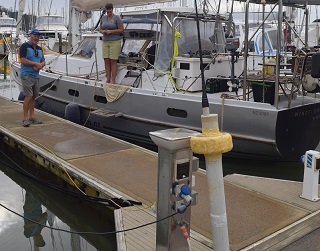
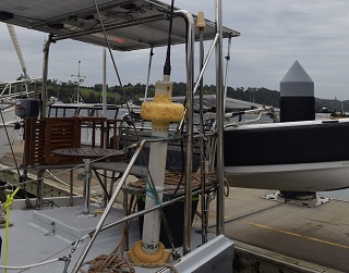
- John & Lyn Martin ... for releasing the Floater well off shore from their yacht "Windflower"
- to the several people for their encouragment and moral support!
|