I've lost interest in this project for the moment, but one day the 'Floater Mojo' will return!
The ZL1SIX Ocean Floater #2 (OF2) project objective ...
... to launch a free drifting buoy into the southern Pacific Ocean and track it via HF radio telemetry as it drifts with the winds, tides, and currents from southern New Zealand generally east towards South America.
OF2 is based on QRP-Labs hardware (modified U3S TX + QLG1 GPS) controlled by a PICAXE 08M2 to conserve power from the solar charged lithium batteries and ensure the same reliable operation as OF1.
It will transmit WSPR once an hour followed by several minutes of JT9 telemetry sending position, direction, speed, battery & solar volts, and temperature. The 30m band will probably be used as a compromise between day and night propagation, but 20m is another option (antennas have been built for both bands).
OF2 will use a more efficient center loaded vertical antenna with a 'ground' directly in the sea water. The Tx output power will be at least 1W to provide better DX coverage than OF1 (100mW to a base loaded whip).
Build notes and progress (updated 12 Nov 2019):
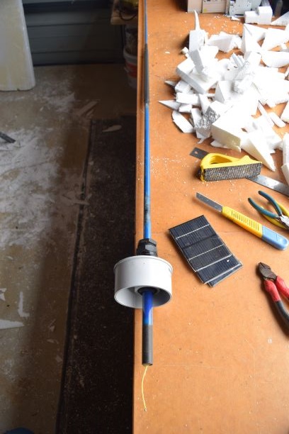
... HF whip antennas for 30m and 20m built using plumbing fittings, fishing rods and tapered SS whips
... buoy body and anti-bobbing flotation ring assembled
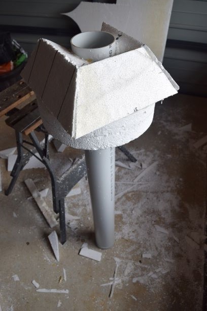
... solar panel mounting surface construction
... preliminary solar panel output tests at various sun angles and draft power budget (result was marginal)
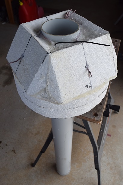
... solar panel mounting surface modifications to double the number of cells and orientate for better sun angle
 during winter and at southern latitudes (>50 degrees south).
The ZL1SIX Ocean Floater #2 (OF2) project objective ...
... to launch a free drifting buoy into the southern Pacific Ocean and track it via HF radio telemetry as it drifts with the winds, tides, and currents from southern New Zealand generally east towards South America.
OF2 is based on QRP-Labs hardware (modified U3S TX + QLG1 GPS) controlled by a PICAXE 08M2 to conserve power from the solar charged lithium batteries and ensure the same reliable operation as OF1.
It will transmit WSPR once an hour followed by several minutes of JT9 telemetry sending position, direction, speed, battery & solar volts, and temperature. The 30m band will probably be used as a compromise between day and night propagation, but 20m is another option (antennas have been built for both bands).
OF2 will use a more efficient center loaded vertical antenna with a 'ground' directly in the sea water. The Tx output power will be at least 1W to provide better DX coverage than OF1 (100mW to a base loaded whip).
Build notes and progress (updated 12 Nov 2019):
... HF whip antennas for 30m and 20m built using plumbing fittings, fishing rods and tapered SS whips
... buoy body and anti-bobbing flotation ring assembled
... solar panel mounting surface construction
... preliminary solar panel output tests at various sun angles and draft power budget (result was marginal)
... solar panel mounting surface modifications to double the number of cells and orientate for better sun angle
... Styrofoam off-cuts and flakes everywhere!
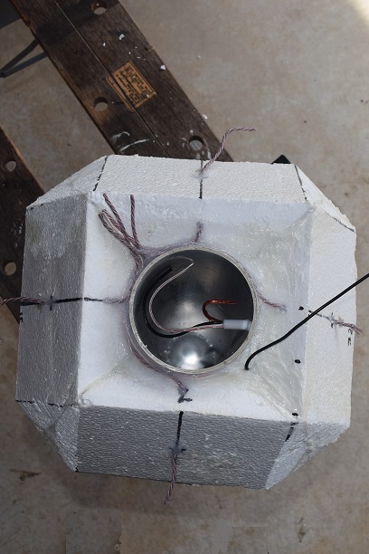
... solar panel mounting surface completed. Solar panel wiring, GPS antenna coax, and 'ground' wire added
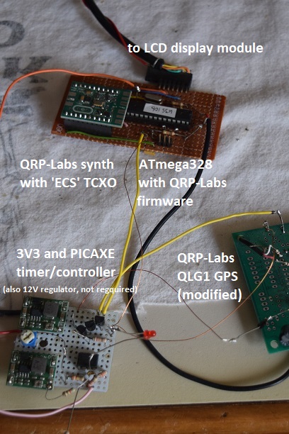
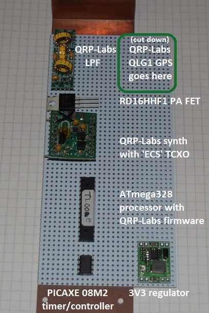
... prototype transmitter on test, and working out the final layout
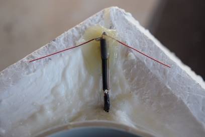
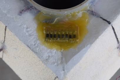
... GPS dipole with 1/4 WL 'stub' (to suppress HF getting to the GPS input), and solar panel isolation diodes
Further build notes and photos will be added here as it happens ...
Some additional comments/info that may be of interest ...
The solar cells on OF2 will be sitting 10cm (4") above the water line, and water will be frequently washing over them so salt will not build up.
The concern is a build up of marine growth below the water line gradually dragging the buoy lower in the water over the long term.
A coat of anti-fouling paint will help, but not for ever without a periodic clean down (which, for obvious reasons, will not happen!)
OF1 (100mW TX) ran for over a year on D-cells, but OF2 may circulate in the South Pacific Gyre for several years (if it physically survives).
The 150mW from OF1 was not enough RF output power for good signal strength with the low efficiency of the short loaded whip antenna.
D-cells in sufficient quantity to run OF2 at 1W output for a few minutes an hour (even for 1 year) would be large and expensive.
They would be physically too large for the 15cm dia x 100cm long (6" x 40") buoy body (I don't want bigger), so solar charging is required.
Even a small vessel such as OF1/OF2 has considerable buoyancy. The battery weight in OF1 was no where near enough to set the desired waterline.
Several kg of additional ballast was required (a billet of round steel weighing about 3kg/7lb was set into the bottom of the buoy tube with epoxy resin).
The majority of the ballast weight needs to be as low as possible to help keep the vertical whip antenna upright (wind load).
In that respect lead ballast would have been better, but I had the steel on hand.
All the electronics in OF1 were shut down when not operating by a 'housekeeping' processor that consumed about 40mWhr per day. OF2 will be similar.
The 'housekeeping' is separate and simple. That methodology keeps the U3S firmware intact (it is proven very reliable ... and I am not a 'code writer').
OF2's 1W RF output will be the biggest power consumer (about 4.8Whr per day). Efficiency gains in the PA will be significant. Possible Class-E PA?
OF1 was set to transmit twice per hour. Once per hour for a slow moving object would probably be enough.
1 or 2 transmissions a day might even be enough, but no fun in that! Buoy progress is akin to watching grass grow, so a more regular signal will be nice.
Unless testing proves otherwise, the power budget calculations say 2 transmissions per hour will work with OF2, with several days of battery autonomy.
Anyway, the 'housekeeping' in OF2 will monitor the battery and skip transmissions if the battery is low due to poor solar charge.
An ATmega328 will work at 16 or 20 MHz with a 3V3 supply ... out of spec, but they still work. I've tried dozens of them ...
Of course one wouldn't do that in a commercial product, but this is an amateur project working on a 'one off / suck it and see' basis.
With a TCXO as a Si5351a reference there is no need for repeated calibration ... using a TCXO will keep an HF transmitter within a few Hz.
U3S firmware does not save calibrations of less than 10Hz (to extend EEPROM life), so anything less is lost during the 'housekeeping' power off.
The 'housekeeping' can reset the U3S to make use of the new calibration scheme in later U3S firmware, but not really necessary with a TCXO.
Not much 'warm up time' is required for a straight WSPR trace when using a TCXO/Si5351a.
With Vbk applied to the GPS it usually locks within seconds, but time is still allowed for a GPS 'cold start'.
A 'cold start' may be required if the 'housekeeping' has the system shut down for an extended period due to low solar charge.