Huawei R4875G1 Switch Mode Power Supply Unit (aka 'server rectifier')
March 2022 ... The old Cosel 1500W SMPSU used to power my W6PQL 6m amplfier is marginal. The 1000W RF output and 70% efficiency of the PA means that the PSU is working close to its limit (1000W / 70% efficiency = 1429W DC input ... plus 30 Watts or so powering the cooling fans, bias supply, and relays = 1459W), so I decided to upgrade to a 'computer server supply' with a higher power rating.
There are plenty of 'server supply' or 'server rectifier' offerings via AliExpress, but most are used "pulls" that may possibly have had many years of continuous use. However, I did find one vendor ('Tonifishi D automatic Store') who was offering brand new Huawei R4875G1 4kW units, still in their original factory packaging.
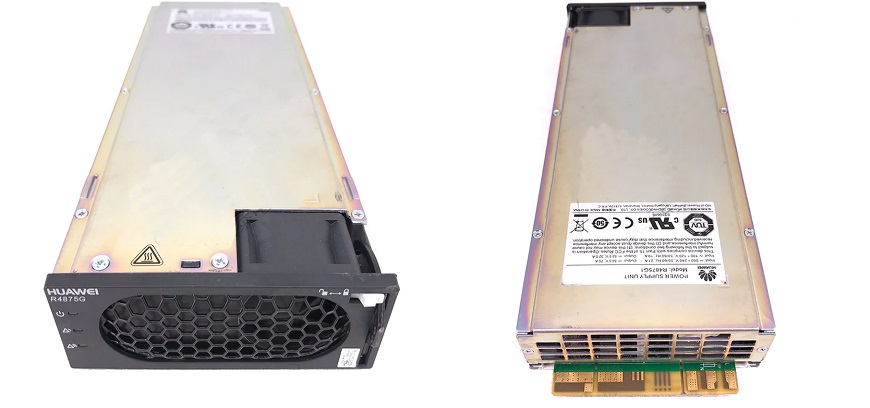
The Huawei R4875G1 'server supply' is not as common as the R4850G2 version for which there is a lot of information available on the Internet, but the Huawei support web site has the R4875G1 user manual which contains the basic specifications and a diagram of the edge connector pin assignments.
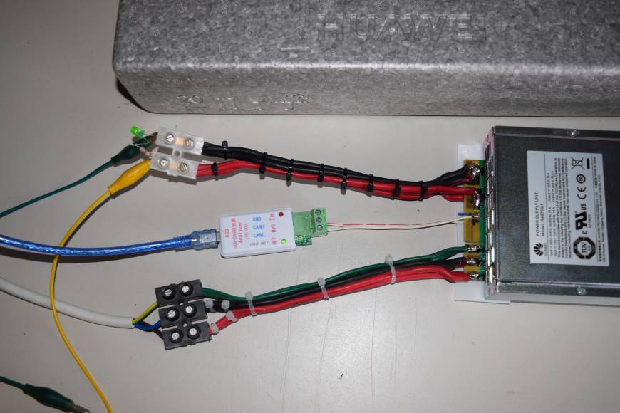
The appropriate pins were connected as shown below (using the R4850G2 connection information on the Internet as a guide) ...
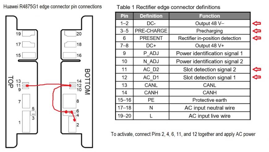
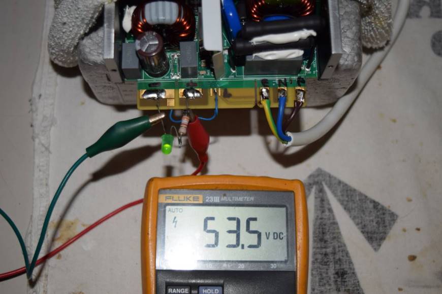
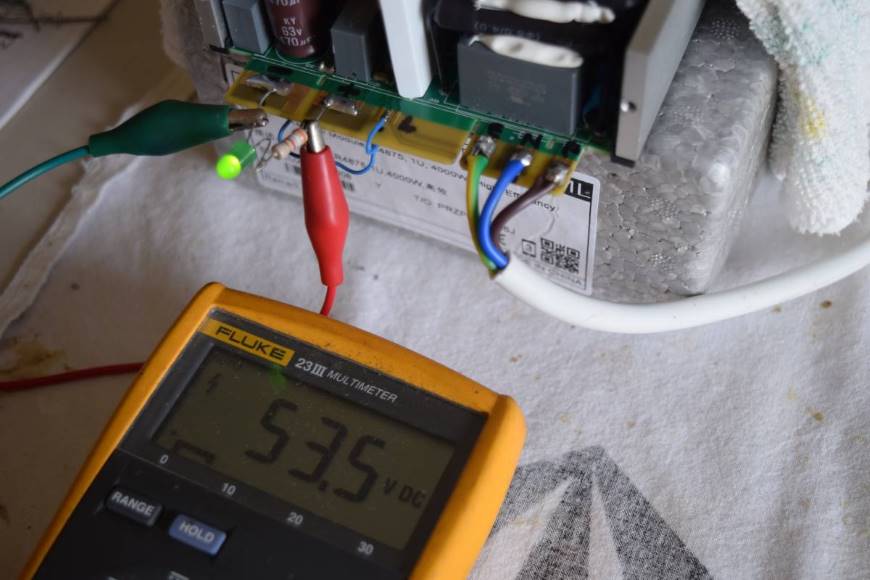
And the server supply powered up ...
June 2022 update ...
Despite what the model number might imply, the default output voltage of the R4875G1 supply is 53.5V DC which is higher than the Vdd specification for the BLF188XR LDMOS device used in my W6PQL 6m amplifier. However, it is possible to re-program the default start-up voltage (and other parameters, like the current limit) of the R48xx series power supplies via their 'CAN' communications bus.
A USB<>CAN adapter bundled with a suitable USB cable was ordered via AliExpress (search for USB to CAN Bus Converter Adapter)
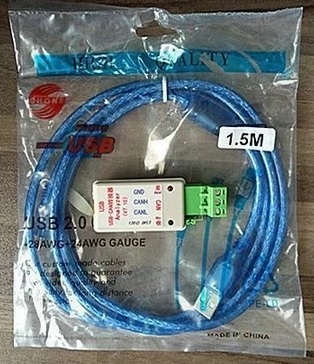
note: adapter V7.10 was shown in the images on AliExpress, but adapter V8.00 was supplied
The following video was useful to get aquainted with the overall programming proceedure before configuring the software as below:
https://youtu.be/_IKTpq7bXoI
These steps were followed to set everything up:
An installer for the Windows driver for the CAN adapter device's USB port was downloaded from here:
https://github.com/SeeedDocument/USB-CAN-Analyzer/tree/master/res/Driver/driver%20for%20USBCAN(CHS40)/windows-driver
The CH341SER.EXE file was downloaded and run to install the required serial port driver on my computer (laptop with Win8.1)
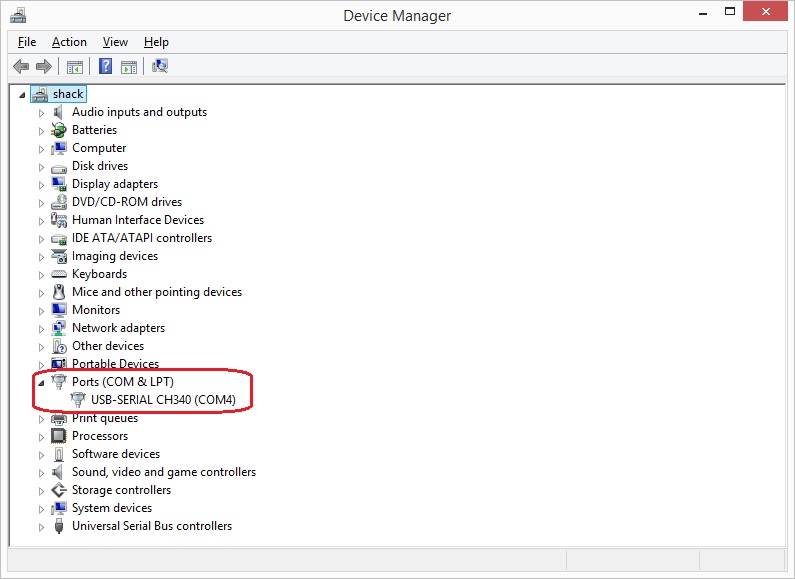
The CAN adapter device was then plugged into a USB port on the laptop and Windows Device Manager was checked to verify it was accepted and the COM port number was assigned. Mine was listed as USB-SERIAL CH340 (COM4)
The CAN adapter was then connected to pins 13 and 14 of the R4875G1 edge connector with a short piece of thin twin conductor cable (note the CANH and CANL 'polarity' according to the diagram above). To do this the bottom cover of the R4875G1 had to be removed, so I took the opportunity to solder some heavy duty wires to connect to the AC input and DC output pads on the edge connector.
When selecting the wire size keep in mind that at 'full power' the 230V AC input could draw up to 21A and the DC output could supply up to 75A (according to the PSU label). I used a pair of 20A rated wires on the AC input (mainly to connect to the pads on both sides of the PCB), and three 20A rated wires on the DC output (two wires to the large pads on one side of the PCB, and one wire to the smaller pad on the other side of the PCB).
When reassembling the R4875G1 a thin sheet of insulation was placed between the solder joints/wires and the bottom cover of the PSU to guard against short circuits. I used an offcut of 0.5mm thick Teflon sheet that happened to be on hand, but several layers of PVC tape would have done just as well.
The USB-CAN(V7.20).exe software to program the R4875G1 via the CAN adapter was downloaded from
https://github.com/SeeedDocument/USB-CAN-Analyzer/tree/master/res/V7.20
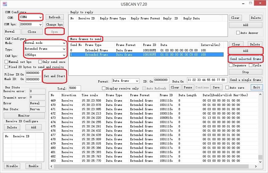
Run the USB-CAN(V7.20).exe program and enter the following settings:
'Com Configure:'
'COM:' COM4 (or your CAN adapter's assigned COM port number)
'CAN Configure:'
'Mode:' select Normal from the drop down list
'Type:' select Extended Frame from the drop down list
'CAN bps:' select 125kbps from the drop down list
Now click on 'Open' back up in the 'Com Configure' area and a stream of CAN data should appear in the table at the bottom.
To make an on-line or 'live' change in the output voltage, add a line to 'More frames to send:'
Click on 'Add'
Click on the Frame ID number '00000000' to highlight it and edit it to read 108180FE
Click on the Data number '00 01 02 03 04 05 06 07' to highlight it and edit it to read 01 00 00 00 00 00 C8 00 (note: 01 00 ....... )
Click on 'Set and Start', then click on the 'Send No' (0) to highlight the whole line, and then click on 'Send selected frame'
The output voltage of the R4875G1 should decrease to 50.0V (depending on the accuracy of the multi-meter!)
Note: this change is temporary, and after a minute or so the output voltage will revert to the programmed default start up voltage.
To make an off-line or default 'start up' voltage change, add another line to 'More frames to send:'
Click on 'Add'
Click on the Frame ID number '00000000' to highlight it and edit it to read 108180FE
Click on the Data number '00 01 02 03 04 05 06 07' to highlight it and edit it to read 01 01 00 00 00 00 C8 00 (note: 01 01 ....... )
Assuming 'Set and Start' is still active, click on the 'Send No' (1) to highlight the whole line, and then click on 'Send selected frame'
Cycle the mains input power on the R4875G1 (power off - wait - power on), and the output voltage should start at 50.0V and stay there.
Note that the lines in the 'More frames to send' information box will be saved in the program's config file, so they will pre-filled the next time the programming software is started.
The 'on-line/live' and 'off-line/default' (start up) voltages can be calculated as follows:
required Voltage x 1024 and convert the Decimal result to Hexadecimal with an on-line converter
(https://www.rapidtables.com/convert/number/decimal-to-hex.html)
e.g. for 49.8 Volts at start up ... 49.8 x 1024 = 50995.2 ... 50995 converted to Hexadecimal = C733
This is entered into 'More frames to send:' with 'Frame ID' as 108180FE and 'Data' as 01 01 00 00 00 00 C7 33
Then click on 'Send selected frame'
Here is a list of useful 'Data' numbers to set various default start up voltages:
01 01 00 00 00 00 C0 00 = 48V
01 01 00 00 00 00 C8 00 = 50V
01 01 00 00 00 00 D8 00 = 52V
01 01 00 00 00 00 DC 00 = 55V
01 01 00 00 00 00 E8 00 = 58V
The maximum 'Data' setting for the default start up voltage is 01 01 00 00 00 00 E9 99. Any higher 'Data' entry returns a programming error (code '21'). E999 Hex = 59801 / 1024 = 58.4V. When programmed with E999 the R4875G1 output voltage as read on my Fluke multimeter is 58.3V and the power supply's internal voltage reading returns E9C0 which is 58.437V.
Apparently other parameters can be programmed according to the following table (not all have been tested/confirmed here):
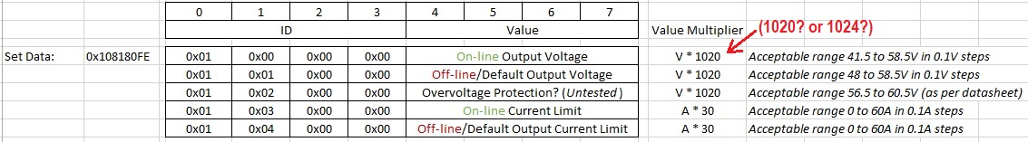
The Overvoltage protection programming was tested and any 'Data' entry higher than F200 returns an error. F200 Hex = 61952 / 1024 = 60.5V ("as per datasheet"), so it seems that the correct 'Value Multiplier' for voltage calculations is 1024.
The current limit setting might be useful to prevent damage to the LDMOS device in an amplifier?
August 2022 : This power supply now runs my W6PQL 6m amplfier.
|