Project : Simple Remote Control
March 2025: this started as a project to remotely control the rotator on the 4 x 6 element LFA 6m array ... to 'park' it into the wind and minimise damage during storms. Then the idea expanded to control the whole 6m station using my laptop to remotely access my shack computer via AnyDesk.
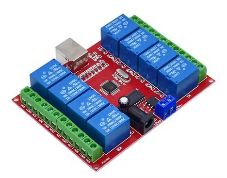
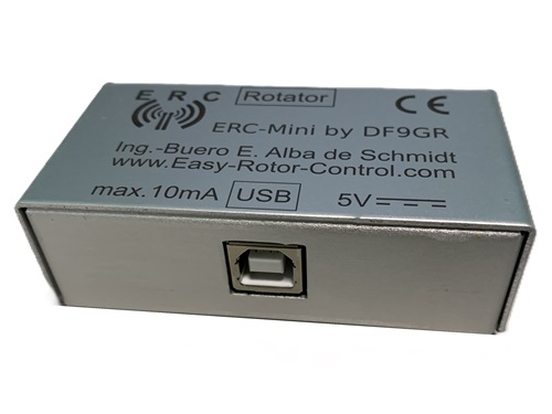
Internet searches found an 8-way USB relay switching module to turn equipment on/off (AliExpress, ~USD8 + tax + shipping), and a nicely packaged Easy-Rotor-Control interface (complete with connecting cables) to computer control the rotator (the ERC-mini for ~USD99 + tax + shipping from DF9GR) ...
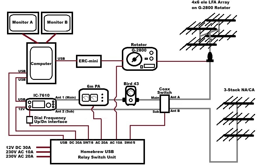
This block diagram shows the connections ...
Connecting the ERC-mini interface was easy using the USB and rotator cables supplied. The 'set-up' and 'control' software were downloaded via the links on the ERC-mini's instruction sheet. The 'set-up' software (EFRC-Mini_V11) was run to configure the USB port, rotator type and rotator settings (e.g. slow speed), then to calibrate the computer screen's azimuth direction indicator.
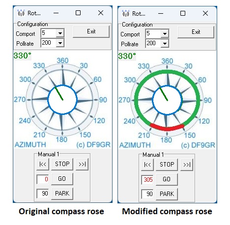
Rotator control from the computer uses the 'control' software (RC-G_V10). The on-screen antenna direction indicator uses a background .jpg image found in the RC-G_V10 files folder. This was edited to add green and red zones on the compass rose to show rotation restrictions to be observed here. Here is the difference between the 'original' and my 'modified' rotator control screens ...
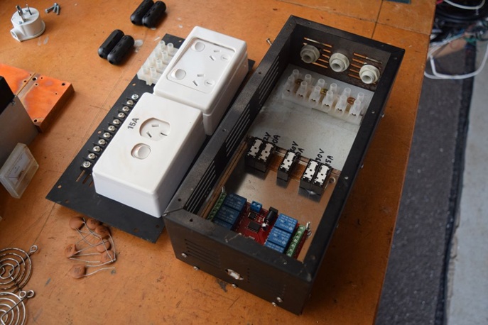
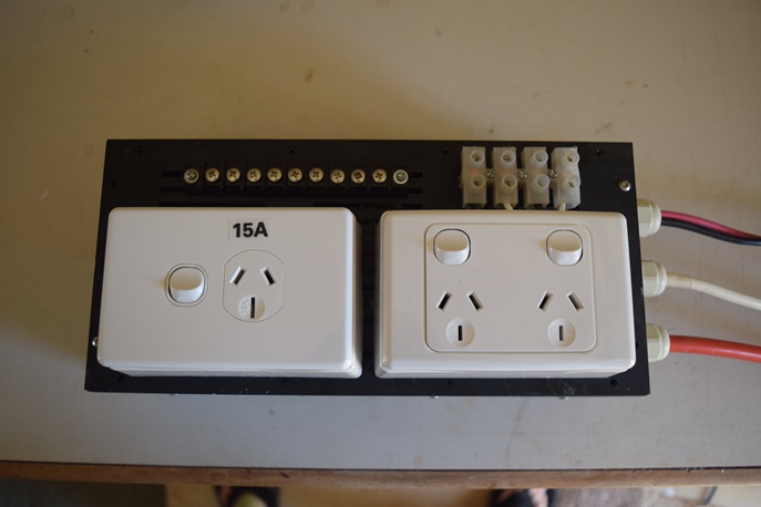
The USB relay switching module was mounted in a recycled metal case from my junk box. High current relays were added to switch a 12V 30A DC feed for the radio, and two 230V AC feeds: a standard 10A AC feed for the rotator and a special 15A (20A) AC feed to run the 6m PA's power supply ...
Windows software for the USB relay module was difficult to find. The module uses an HID USB protocol rather than a Com Port protocol. Eventually I found two Windows apps that could drive the HID interface. (There are Com Port versions of these relay modules available which might be a better option?)
One app was a very simple freeware program ('RelayCtl' at https://sourceforge.net/projects/usb-relay-hid/), but it didn't offer many configuration options or the ability to custom label the computer screen 'buttons' with unique names to easily identify the various switch functions.
The other software ('Relay Controller' at https://www.rightbooth.com/products.html) did all those things and was available as a free trial with an option to register for USD29 + tax (suppresses a pop-up screen that randomly appears prompting you to register!) After experimenting with both applications it was clear that the fuller featured payware app was going to be VERY useful for my purposes, so I bought it (the registration code was delivered immediately via email).
After installing my remote system on a test computer I realised it didn't have frequency control. The dial frequency was visible in JTDX/WSJT-X via CAT, but no way to change it ... however, Icom have frequency up/down on pin 3 of the mic socket (for the "UP/DN" buttons on Icom hand mics). Years ago I built a frequency up/down interface for my IC-7600 using two push switches and a resistor mounted in a small plastic box (info on pg. 23 of the IC-7600 manual) ...
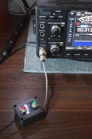
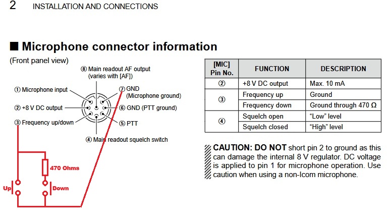
This little box also works on the IC-7610, so a cable was added to connect it to two of the USB relay control board outputs (switch 7 and 8). These two relays were then programmed in the payware app to act as momentary switches when clicked with the left mouse button (press=on / release=off). The computer screen switch buttons were labeled "Freq up" and "Freq dwn" respectively. This very simple 'up/down frequency step tuning' works well for what I need.
Here are all 8 uniquely labelled USB relay control board switch buttons as they appear on the computer desktop ...
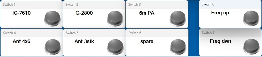
Clicking on a grey button activates the associated relay and the button colour changes to orange (red?) to indicate the 'ON' status.
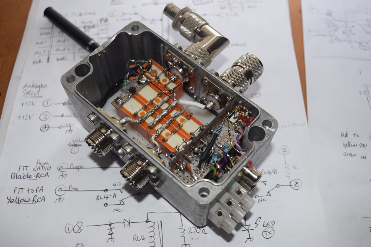
Now working on a remote controlled 'antenna selector relay box' (aka the "Coax Switch" in the block diagram above). This is a 'special configuration' to interchange the two 6m antenna arrays that are in use here between the two antenna ports on the IC-7610 radio using the USB remote switch ports 4 and 5. This will allow the 7610's Main and Sub receivers to swap between the two arrays ... or to use both antenna arrays combined together for receive only.
The small vero board is a simple 'diode/transistor logic' interlock on the PA's PTT line so the amplifier will only operate when one or other array is connected to the "IC-7610 Ant 1 (Main Rx) and PA port". The PA will not key if there is no antenna selected, or if both arrays are combined to the 'Main Rx and PA' port.
Here is the progress so far, just the final wiring of the orange coloured relays and the 'status LEDs' to be done ...
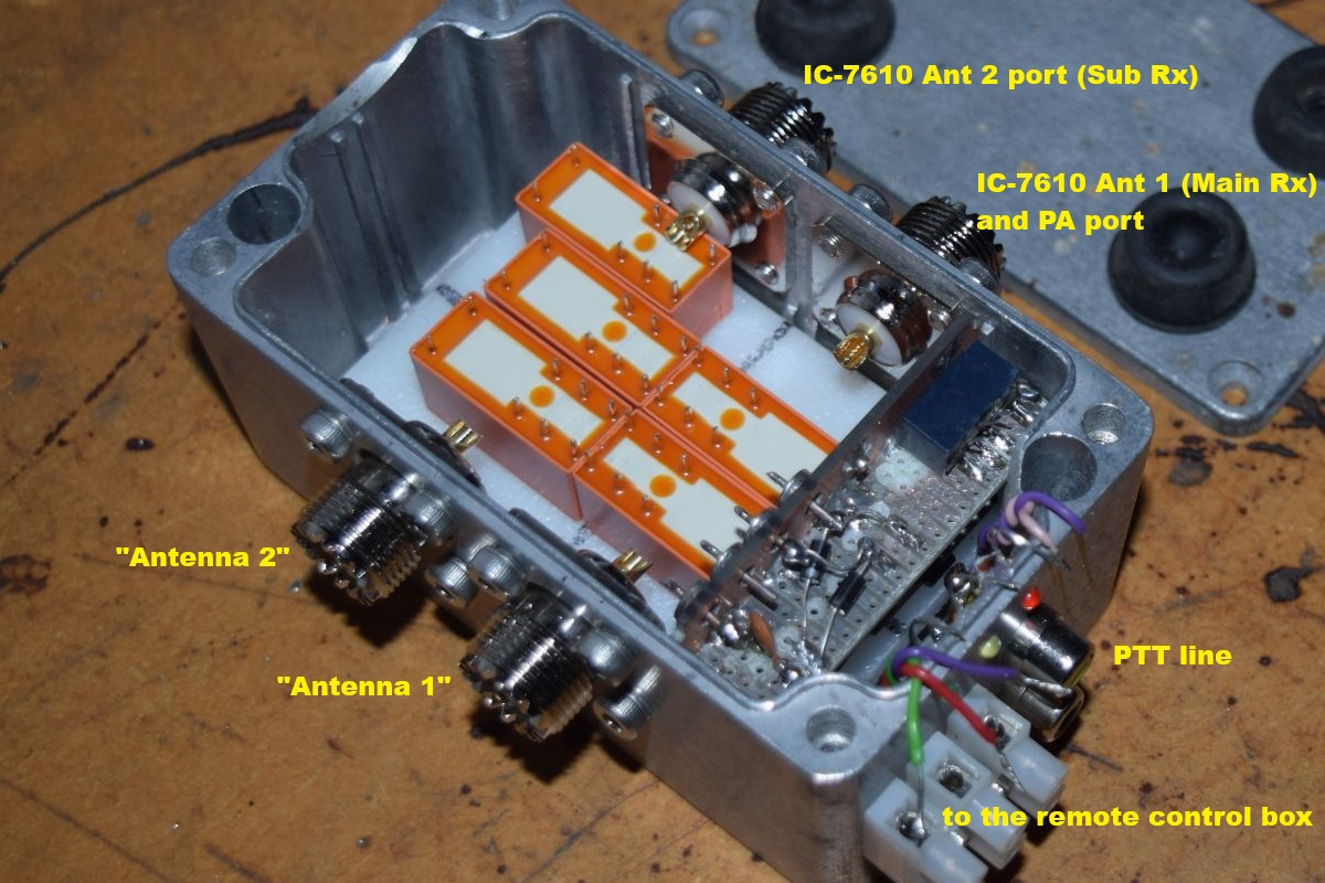
The four relays grouped in the middle operate in paralleled pairs to accommodate the PA's full power, and the single relay offset to the upper right is to further isolate the IC-7610's Ant 2 Sub receiver port from the PA as a precaution (e.g. the IC-7610's Ant 2 / Sub RX port is grounded on TX). Further information on using these inexpensive relays for switching RF can be found at: W6PQL's web site and at Antenna-Amplifier's web site - example 1, Antenna-Amplifier's web site - example 2, Antenna-Amplifier's web site - example 3.
April 2025: After completing the antenna change-over relay wiring and connecting its control board, I discovered that the miniture relay used in my 'diode/resistor PTT logic' circuitry is the rare/unique variety that has a 'polarized coil'. This miniture relay was from my 'junk box' and simply would not work with the coil voltage polarisation change in my 'logic' circuit. Some non-polarized miniture relays (normal relays!) are on order via AliExpress so the project can be completed.
The new relays arrived and, damned me, they were also polarized despite carefully selecting a make/model that was supposed to suit my purpose. Grrrr!! Rather than order more relays and wait again for them to arrive, I added a bridge recifier between my 'diode/resistor PTT logic' circuit and the relay's coil so it always sees the correct polarity. Now it is switching properly.