Loop Filter for Receiver
A receiver for 80m was constructed
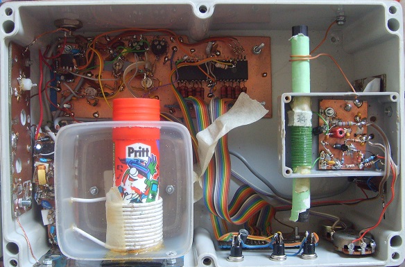 This receiver uses a PLL with 10kHz reference frequency. (The 'Pritt' is a permeability variable
incremental tuner- a variable inductor used for tuning the receiver +/-5 kHz away from fixed 10kHz step).
This receiver uses a PLL with 10kHz reference frequency. (The 'Pritt' is a permeability variable
incremental tuner- a variable inductor used for tuning the receiver +/-5 kHz away from fixed 10kHz step).
 The 10Khz reference is derived from a 5.94Mhz ceramic oscillator. By adjusting the frequency
of the 5.94Mhz reference, the receiver can be tuned between the 10kHz steps. This adjustment
is slightly different at the lower end and upper end of the received band (3.0 .. 3.99Mhz).
The performance of such a receiver is determined a great deal by the loop filter:
The 10Khz reference is derived from a 5.94Mhz ceramic oscillator. By adjusting the frequency
of the 5.94Mhz reference, the receiver can be tuned between the 10kHz steps. This adjustment
is slightly different at the lower end and upper end of the received band (3.0 .. 3.99Mhz).
The performance of such a receiver is determined a great deal by the loop filter:
 The opamp used in the loop filter should be fast with low noise, and here the input range includes 0v.
The PLL reference freq (here 10kHz) must be suppressed by the loop filter to avoid feedthough
to the VCO. If this is not successful, then a very strong signal (like S9+40dB) is heard on the
receiver when it is tuned one 10kHz step off the very strong signal. The loop filter has a low pass
response but it is not sufficient to mask this strong signal. [The 10kHz reference appears at the output of
the loop filter to create sidebands on the VCO at +/10kHz]. So additional filtering is necessary.
This filtering must not increase the phase shift too much at the loop natural frequency. One approcah is
to include a notch filter at the PLL reference frequency between the output of the loop filter and the
VCO. Another approach used here, is to include another low pass filter between the output of the loop
filter and the VCO. This arrangement is described by K0ABP in EDN September 1978 (Vol 27 # 18) uses a low pass
filter at 10* the loop natural frequency with a Q of 1.414 (a damping factor of 0.707).
The opamp used in the loop filter should be fast with low noise, and here the input range includes 0v.
The PLL reference freq (here 10kHz) must be suppressed by the loop filter to avoid feedthough
to the VCO. If this is not successful, then a very strong signal (like S9+40dB) is heard on the
receiver when it is tuned one 10kHz step off the very strong signal. The loop filter has a low pass
response but it is not sufficient to mask this strong signal. [The 10kHz reference appears at the output of
the loop filter to create sidebands on the VCO at +/10kHz]. So additional filtering is necessary.
This filtering must not increase the phase shift too much at the loop natural frequency. One approcah is
to include a notch filter at the PLL reference frequency between the output of the loop filter and the
VCO. Another approach used here, is to include another low pass filter between the output of the loop
filter and the VCO. This arrangement is described by K0ABP in EDN September 1978 (Vol 27 # 18) uses a low pass
filter at 10* the loop natural frequency with a Q of 1.414 (a damping factor of 0.707).
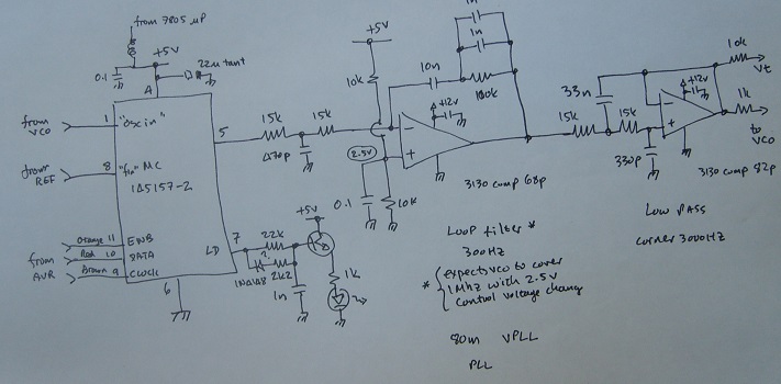 The circuit shown above uses the single ended output of the phase detector. Remember that the loop filter
is a low pass filter- it can't reduce noise below the loop natural frequency. [So in the example circuit,
the loop frequency should be below 100Hz rather than the 300Hz shown]. But by using the double ended phase
detector outputs, some common mode rejection is possible (with a doubled up loop filter configuration).
This really has no effect unless the differential paths really are differential (gains must match).
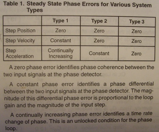
PLL Steady States for different Types (not orders)
The circuit shown above uses the single ended output of the phase detector. Remember that the loop filter
is a low pass filter- it can't reduce noise below the loop natural frequency. [So in the example circuit,
the loop frequency should be below 100Hz rather than the 300Hz shown]. But by using the double ended phase
detector outputs, some common mode rejection is possible (with a doubled up loop filter configuration).
This really has no effect unless the differential paths really are differential (gains must match).
PLL Steady States for different Types (not orders)
 Andy K0ABP wrote articles on PLL design in EDN 1978 (vol 26 #10 and Vol 26 #19). These articles were reprinted
in Motorola AR254 and some sections are shown below.
Andy K0ABP wrote articles on PLL design in EDN 1978 (vol 26 #10 and Vol 26 #19). These articles were reprinted
in Motorola AR254 and some sections are shown below.
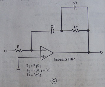 Third order loop filter, together with another integrator (vco), this creates a Type 2 system.
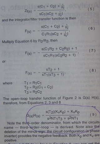 Transfer function. T1,T2,T3 are time constants in seconds.
Kp volts/rad, Kv rad/sec/volt, N frequency divisor
Transfer function. T1,T2,T3 are time constants in seconds.
Kp volts/rad, Kv rad/sec/volt, N frequency divisor
 Solve for T1,T2,T3 with phase margin 45 degrees.(there is no damping factor here)
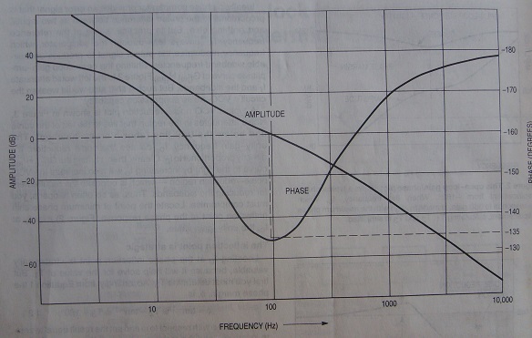 phase margin of 45degrees ensures stability
Here's a sample solver:
Sub r2p(ByVal x As Single, ByVal y As Single, ByRef mag As Single, ByRef ang As Single)
mag = Math.Sqrt(x * x + y * y)
ang = Math.Atan2(y, x) * 180 / Math.PI
End Sub
Sub docalc()
Dim fo As Single = 100 ' 5000/50
Dim phi As Single = 45
Dim Kp As Single = 0.19 ' V/Rad
Dim Kv As Single = 10600000.0 ' rad/s/V
Dim N As Single = 3390
Dim m4 As Single = fo * 2 * Math.PI
Dim m7 As Single = phi * Math.PI / 180
Dim m5 As Single = Kp * Kv / N
Dim tmp As Single
tmp = (1 / Math.Cos(m7)) - Math.Tan(m7) ' (sec - tan )
Dim m3 As Single = tmp / m4 '/wo T3
Dim m2 As Single = 1 / (m3 * m4 * m4)
Dim mag1, ang1 As Single
r2p(1, m2 * m4, mag1, ang1)
Dim mag2, ang2 As Single
r2p(1, m3 * m4, mag2, ang2)
Dim m1 As Single = mag1 / mag2
m1 /= m4 * m4
m1 *= m5
Debug.Print("T1= " + m1.ToString)
Debug.Print("T2= " + m2.ToString)
Debug.Print("T3= " + m3.ToString)
Dim wo As Single = 1 / (Math.Sqrt(m2 * m3))
Debug.Print("(Wo " + (wo / (2 * Math.PI)).ToString + "Hz)")
End Sub
test output
T1= 0.003633087
T2= 0.003842341
T3= 0.0006592413
(Wo 100.000001872062Hz)
phase margin of 45degrees ensures stability
Here's a sample solver:
Sub r2p(ByVal x As Single, ByVal y As Single, ByRef mag As Single, ByRef ang As Single)
mag = Math.Sqrt(x * x + y * y)
ang = Math.Atan2(y, x) * 180 / Math.PI
End Sub
Sub docalc()
Dim fo As Single = 100 ' 5000/50
Dim phi As Single = 45
Dim Kp As Single = 0.19 ' V/Rad
Dim Kv As Single = 10600000.0 ' rad/s/V
Dim N As Single = 3390
Dim m4 As Single = fo * 2 * Math.PI
Dim m7 As Single = phi * Math.PI / 180
Dim m5 As Single = Kp * Kv / N
Dim tmp As Single
tmp = (1 / Math.Cos(m7)) - Math.Tan(m7) ' (sec - tan )
Dim m3 As Single = tmp / m4 '/wo T3
Dim m2 As Single = 1 / (m3 * m4 * m4)
Dim mag1, ang1 As Single
r2p(1, m2 * m4, mag1, ang1)
Dim mag2, ang2 As Single
r2p(1, m3 * m4, mag2, ang2)
Dim m1 As Single = mag1 / mag2
m1 /= m4 * m4
m1 *= m5
Debug.Print("T1= " + m1.ToString)
Debug.Print("T2= " + m2.ToString)
Debug.Print("T3= " + m3.ToString)
Dim wo As Single = 1 / (Math.Sqrt(m2 * m3))
Debug.Print("(Wo " + (wo / (2 * Math.PI)).ToString + "Hz)")
End Sub
test output
T1= 0.003633087
T2= 0.003842341
T3= 0.0006592413
(Wo 100.000001872062Hz)