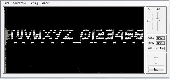
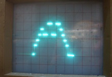
Text display on waterfall
This is a mega16 AVR program and sends characters for display on waterfall. One of 7 tones is sent
(one a time). The carrier is always on and is shown as inter-letter underline on the waterfall.
 This beacon keyer sends text characters as a varying carrier frequency. Each character is comprised
of pixels within a 7x5 matrix. Some characters are narrower and take up less pixels in the x
direction. When there are no pixels in the column at all, the D/A output value is 001 for a
carrier offset of 0 Hertz. If the lowermost pixel of a column is part of the current character,
the D/A output value changes to 010 (or 2); this then becomes carrier offset of +50Hz. However,
if the lowermost pixel isn't required but the pixel immediately above is, the D/A output changes
to 011 (or 3) for a carrier offset of +100Hz. There are no breaks or pauses in the transmitted carrier.
This allows for reduced noise on display (because the carrier is always on) and for more power per pixel
in each column.
This beacon keyer sends text characters as a varying carrier frequency. Each character is comprised
of pixels within a 7x5 matrix. Some characters are narrower and take up less pixels in the x
direction. When there are no pixels in the column at all, the D/A output value is 001 for a
carrier offset of 0 Hertz. If the lowermost pixel of a column is part of the current character,
the D/A output value changes to 010 (or 2); this then becomes carrier offset of +50Hz. However,
if the lowermost pixel isn't required but the pixel immediately above is, the D/A output changes
to 011 (or 3) for a carrier offset of +100Hz. There are no breaks or pauses in the transmitted carrier.
This allows for reduced noise on display (because the carrier is always on) and for more power per pixel
in each column.
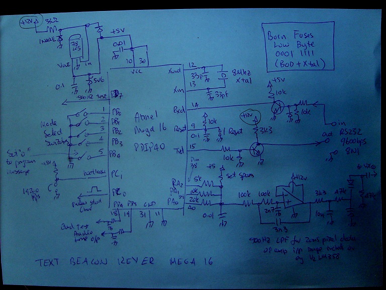
 A D/A circuit is added from the lowermost bits of portA. This D/A is intended to move the frequency
of a crystal controlled oscillator by about 50Hz for each D/A count.
A D/A circuit is added from the lowermost bits of portA. This D/A is intended to move the frequency
of a crystal controlled oscillator by about 50Hz for each D/A count.
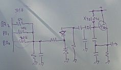 Voltage steered xtal oscillator. When the uP switches an output to '1' level, that output pin is
effectively connected to the supply rail. The capacitor at the D/A output is intended to prevent
power supply noise making its way to the varactor, a small value of 10n or 4n7 is best.
[The D/A Resistor should return to +5v in the drawing above]. The schematic at top of page shows additional
low pass filtering to limit bandwidth of the generated FSK signal.
port bits & directions
portA:
lowermost 4 bits outputs; (msb) b2,b1,b0 (lsb) are D/A output drive pins
b7..b4 are inputs
portB (mode select pins):
b4...b0 are inputs
b7...b5 are outputs
portC
all bits are outputs except for b1 (input pin for bootloader if used)
b0 pulses high at start of character (for 'scope trigger)
portD
all bits are inputs except for b1 and b4 and b5 and b7
b0 UART serial 9600 input with 8Mhz xtal
b1 UART serial 9600 output with 8Mhz xtal
b4,b5 are test only tones, in quadrature
b7 is 500Hz test output (xtal/16000 with !SLOW=0, see mv3)
;
mode select (portB), these inputs are usually at '1' level and determine appearance of transmitted characters
mode pB2 pB1 pB0 single pixel time, column time
0 0 0 0 50mS
1 0 0 1 50mS repeat column
2 0 1 0 50mS (same as mode '0')
3 0 1 1 50mS repeat column (same as mode '1')
4 1 0 0 20,25,33,50,100mS 100mS
5 1 0 1 20,25,33,50,100mS 100mS+100mS repeat column
6 1 1 0 20,25,33,50,75mS 100mS or 75ms*
7 1 1 1 20,25,33,50mS - 100mS+100mS or 50mS+50mS* repeat column (selected with no switch installed)
; b3 is 0 for invert D/A when '0'
; b4 echo send character to serial/prog mode, set '0' to program message
Notice that b4 is latched at device reset. The firmware shows b2..b0 value as decimal mode number,
a miniature bcd switch can be used at pins b2..b0 instead of DIP selector.
* columns that have a single pixel only must be sent in a shorter time (75mS and not 100mS)
[Sending columns that have only a single pixel with reduced column time allows for better appearance of characters
like M and V,but sending all columns with fixed time (repeat) allows for more sophisticated decode/display schemes].
Voltage steered xtal oscillator. When the uP switches an output to '1' level, that output pin is
effectively connected to the supply rail. The capacitor at the D/A output is intended to prevent
power supply noise making its way to the varactor, a small value of 10n or 4n7 is best.
[The D/A Resistor should return to +5v in the drawing above]. The schematic at top of page shows additional
low pass filtering to limit bandwidth of the generated FSK signal.
port bits & directions
portA:
lowermost 4 bits outputs; (msb) b2,b1,b0 (lsb) are D/A output drive pins
b7..b4 are inputs
portB (mode select pins):
b4...b0 are inputs
b7...b5 are outputs
portC
all bits are outputs except for b1 (input pin for bootloader if used)
b0 pulses high at start of character (for 'scope trigger)
portD
all bits are inputs except for b1 and b4 and b5 and b7
b0 UART serial 9600 input with 8Mhz xtal
b1 UART serial 9600 output with 8Mhz xtal
b4,b5 are test only tones, in quadrature
b7 is 500Hz test output (xtal/16000 with !SLOW=0, see mv3)
;
mode select (portB), these inputs are usually at '1' level and determine appearance of transmitted characters
mode pB2 pB1 pB0 single pixel time, column time
0 0 0 0 50mS
1 0 0 1 50mS repeat column
2 0 1 0 50mS (same as mode '0')
3 0 1 1 50mS repeat column (same as mode '1')
4 1 0 0 20,25,33,50,100mS 100mS
5 1 0 1 20,25,33,50,100mS 100mS+100mS repeat column
6 1 1 0 20,25,33,50,75mS 100mS or 75ms*
7 1 1 1 20,25,33,50mS - 100mS+100mS or 50mS+50mS* repeat column (selected with no switch installed)
; b3 is 0 for invert D/A when '0'
; b4 echo send character to serial/prog mode, set '0' to program message
Notice that b4 is latched at device reset. The firmware shows b2..b0 value as decimal mode number,
a miniature bcd switch can be used at pins b2..b0 instead of DIP selector.
* columns that have a single pixel only must be sent in a shorter time (75mS and not 100mS)
[Sending columns that have only a single pixel with reduced column time allows for better appearance of characters
like M and V,but sending all columns with fixed time (repeat) allows for more sophisticated decode/display schemes].
 The lowermost bit of portC is an output that pulses to '1' level at the beginning of each character.
This can be used as trigger for 'scope to show current character on display (the D/A values).
The lowermost bit of portC is an output that pulses to '1' level at the beginning of each character.
This can be used as trigger for 'scope to show current character on display (the D/A values).
 The 9600bps Serial connection is used to program the beacon message, and vary the transmission of characters:
!TILT= was added, (TILT can be 0...+/-3)
The 9600bps Serial connection is used to program the beacon message, and vary the transmission of characters:
!TILT= was added, (TILT can be 0...+/-3)
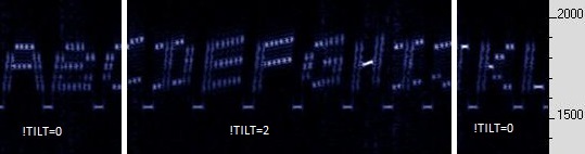 here each column is 5Hz higher than the one before. (This only for the pD4,pD5 audio).
!SLOW= was added, here with !SLOW=4 (pD7 becomes 15.625Hz) from ARGO:
here each column is 5Hz higher than the one before. (This only for the pD4,pD5 audio).
!SLOW= was added, here with !SLOW=4 (pD7 becomes 15.625Hz) from ARGO:
 This is 32 times slower, so the 200mS (repeated; 100mS+100mS) columns each take 6.4 SECONDS.
!SLOW=1 is 2* 100mS speed, !SLOW=2 is 4* the 100mS speed, !SLOW=3 is 8* the 100mS speed, and !SLOW=4 is 32* the 100mS speed.
Reset to 100mS with !SLOW=0
!SAVE saves the message and the current CSET,TILT and SLOW values. Either TILT or SLOW, not both as same time:
tbkm16.zip zip file with .hex file , notes and .apk :
This is 32 times slower, so the 200mS (repeated; 100mS+100mS) columns each take 6.4 SECONDS.
!SLOW=1 is 2* 100mS speed, !SLOW=2 is 4* the 100mS speed, !SLOW=3 is 8* the 100mS speed, and !SLOW=4 is 32* the 100mS speed.
Reset to 100mS with !SLOW=0
!SAVE saves the message and the current CSET,TILT and SLOW values. Either TILT or SLOW, not both as same time:
tbkm16.zip zip file with .hex file , notes and .apk :
 The cset2.apk generates alternate font for the text beacon keyer and dot net programs. The top of each column shows the
direction of plot for the column pixels. Six pixels are shown for each column, but only a maximum of five is used
(anywhere within the column). When pB2="1"each column is sent with same fixed timing by altering pixel duration.
waterfall display program for dot net 3.5
wfalltbk.zip CRC 86F48D0D (Program also creates .wav files)
The cset2.apk generates alternate font for the text beacon keyer and dot net programs. The top of each column shows the
direction of plot for the column pixels. Six pixels are shown for each column, but only a maximum of five is used
(anywhere within the column). When pB2="1"each column is sent with same fixed timing by altering pixel duration.
waterfall display program for dot net 3.5
wfalltbk.zip CRC 86F48D0D (Program also creates .wav files)
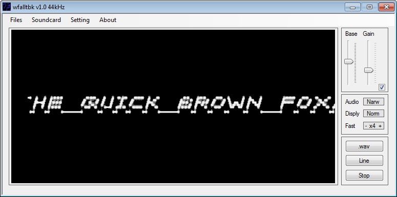 The image above is example waterfall display (see Footnote below).
Example .wav dc.wav 44100 mono repeat column mode. (uncheck 'Att' for volume)
Mega16 Text fixture
The image above is example waterfall display (see Footnote below).
Example .wav dc.wav 44100 mono repeat column mode. (uncheck 'Att' for volume)
Mega16 Text fixture
 The cable at upper right allows for SPI programming of the Mega16. Here a bootloader is programmed into the Mega16
so that if PC1 is "0" as reset time, the RS232 serial connection at pins 14,15 can be used to program the Mega16
instead of the SPI. The bootloader (in the .zip) then works at 19200bps (with 8Mhz xtal) with the RS232 into pins 14,15.
Fuses within the Mega16 are then programmed to change reset vector from $0000 to $1F00 so bootloader runs at reset.
As a simple test of the system, the D/A could alter the uP 8Mhz clock by a few Hz, and the SSB receiver could listen in on
the 18th harmonic (144Mhz).
Replacing COM Port 232 and Transistors
The 232 COM port (and the two transistors) can be replaced with CP2102.
The cable at upper right allows for SPI programming of the Mega16. Here a bootloader is programmed into the Mega16
so that if PC1 is "0" as reset time, the RS232 serial connection at pins 14,15 can be used to program the Mega16
instead of the SPI. The bootloader (in the .zip) then works at 19200bps (with 8Mhz xtal) with the RS232 into pins 14,15.
Fuses within the Mega16 are then programmed to change reset vector from $0000 to $1F00 so bootloader runs at reset.
As a simple test of the system, the D/A could alter the uP 8Mhz clock by a few Hz, and the SSB receiver could listen in on
the 18th harmonic (144Mhz).
Replacing COM Port 232 and Transistors
The 232 COM port (and the two transistors) can be replaced with CP2102.
 The '2102 works on 3.3v levels while the Mega16 works on 5v levels, so the circuit shown uses a PNP emitter follower to
add 0.6v onto the 3.3v levels. (A diode could be used instead of the PNP emitter/base). Sometimes the Txd and Rxd pads of the
2102 are named Rxd and Txd (swapped). [Yes, emitter followers don't need base resistors]
This connection is only required to program the beacon message.
Improved logic level converter
The '2102 works on 3.3v levels while the Mega16 works on 5v levels, so the circuit shown uses a PNP emitter follower to
add 0.6v onto the 3.3v levels. (A diode could be used instead of the PNP emitter/base). Sometimes the Txd and Rxd pads of the
2102 are named Rxd and Txd (swapped). [Yes, emitter followers don't need base resistors]
This connection is only required to program the beacon message.
Improved logic level converter
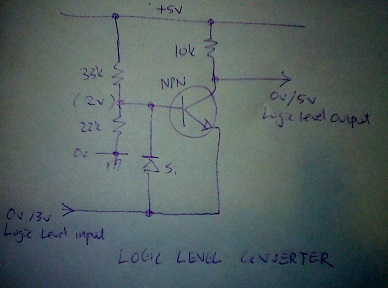 The 33k/22k provide a high impedance base bias of 2v. If the input level is below 1.5v, the output voltage of the circuit
follows the input voltage to within 100mV. If the input logic level exceeds 1.5v, then the output logic level voltage is 5volts.
Footnote
The waterfall image shows frequency in (y) versus scrolling time in (x). This is a result of FFT calculation that converts
from time domain to frequency domain. The FFT algorithm analyses the input audio waveform and determines activity within
narrowly spaced frequency ranges (bins). The waterfall display plots the magnitude of these bins vertically to create the
image. The DSP powered VHF transceiver can create exactly the same image on its inbuilt screen. It is of interest to note
that the 'decoding' of the displayed image is done visually (a 'human decode') and that in contrast the demodulation of PSK
or FSK is done programatically. Acquisition of a PSK or FSK signal is only possible above a threshold SNR of about 5 or 6dB;
below this threshold digital demodulation is not possible. But 'demodulation' of the Text Beacon signal does not have this
limitation. A comparable 'demodulation' occurs when an experienced CW operator is able to copy a signal with SNR less than
0dB (below the noise).
The 33k/22k provide a high impedance base bias of 2v. If the input level is below 1.5v, the output voltage of the circuit
follows the input voltage to within 100mV. If the input logic level exceeds 1.5v, then the output logic level voltage is 5volts.
Footnote
The waterfall image shows frequency in (y) versus scrolling time in (x). This is a result of FFT calculation that converts
from time domain to frequency domain. The FFT algorithm analyses the input audio waveform and determines activity within
narrowly spaced frequency ranges (bins). The waterfall display plots the magnitude of these bins vertically to create the
image. The DSP powered VHF transceiver can create exactly the same image on its inbuilt screen. It is of interest to note
that the 'decoding' of the displayed image is done visually (a 'human decode') and that in contrast the demodulation of PSK
or FSK is done programatically. Acquisition of a PSK or FSK signal is only possible above a threshold SNR of about 5 or 6dB;
below this threshold digital demodulation is not possible. But 'demodulation' of the Text Beacon signal does not have this
limitation. A comparable 'demodulation' occurs when an experienced CW operator is able to copy a signal with SNR less than
0dB (below the noise).