DCF77-synchronized oscillator
last modified in April 2006.
Main Site:
www.qsl.net/dl4yhf
First experiments with a "commercial" OCXO
Once upon a time, I found an ovenned 10-MHz crystal oscillator (OCXO) for a few bucks at a hamfest. It is built in a sealed metal housing, 5 x 5 cm large and 1.5 cm high:
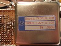
(note: this shiny brass enclosure will be 'dremelled
open' as the story continues ! )
I wondered about the accuracy and stability of this thing. Since I don't have a rubidium- or cesium frequency standard to compare the frequency with, a wireless reference signal was needed. Several options are possible, including LORAN-C (which is due to close down), GPS (which is difficult if you don't want to install an outdoor antenna, and requires a suited receiver), TV-line sync signals from certain broadcasters, and some longwave transmitters.
The first choice was the DCF77 time signal transmitter. It sends a carrier on 77.50000 kHz, but it's amplitude- and phase modulated. But the signal is strong in this part of Germany, so I expect the signal travels via groundwave propagation (futher tests may prove this, or not..). So the first step was to build a simple active antenna, actually a ferrite loop which also acts as a preselector. Here are the schematics and prototype:
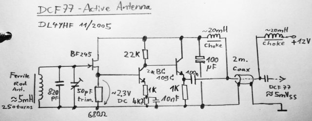
Both supply voltage and received signal run through the inner connector of the thin coax ("microphone cable").
To keep everything simple, the idea was to divide the oscillator frequency down to 77.5 kHz, and later use that in a phase-comparator (based on an analog multiplier), followed by a lowpass filter. The output of the lowpass filter would ideally be a DC signal which could later be used to steer a phase-locked loop to keep the OXCO synchronized with the DCF77 carrier (I didn't know if the OXCO was voltage-controllable at that time; it had an input pin which didn't seem to have a function at all).
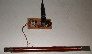
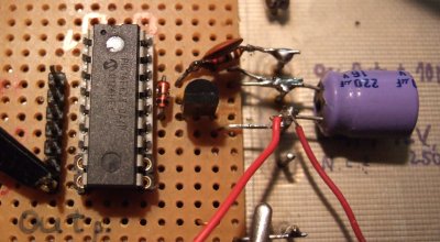
The first step was to build a digital frequency divider from 10 MHz to 77.5 kHz. Ok, 10 MHz divided by 77.5 kHz is 129.0322581... not an integer ratio, not easy to realize with standard components. But it was simple with a programmable microcontroller. If you are familiar with PIC programming, look into this PIC assembly sourcecode. Besides the PIC and a 5-V-regulator, no extra hardware is required for the divider. It was glued to the OCXO in the first prototype, which looked like this:
So I used a PIC16F628, clocked with 10 MHz, to produce a square wave with exactly 77.5 kHz. The 77.5 kHz square wave only has a neglectable jitter, but the sidebands caused by that jitter are outside the passband of the loop filter (which will tie the VOCXO to the DCF reference later). It seemed acceptable for an initial 'proof of concept' .
DCF77 reception test ( under adverse conditions ! )
The output from the PIC-based frequency divider was used as the trigger signal of a digital scope on channel 2, while channel 1 was connected to the active DCF antenna. The scope was set into "average" mode which effectively cancels unwanted noise (a kind of correlation). There was a lot of noise, for example from a TV set nearby which produced a strong signal at 5*15.625 kHz = 78.125 kHz !
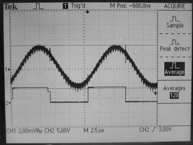
Now the scope image was observed over a longer time period. The upper curve (= smoothed DCF77 carrier) moved slowly across the oscilloscope screen. The lower curve is the 10 MHz oscillator signal divided down to 77.5 kHz. After 7 minutes, the upper sine wave had moved for 360 degrees and appeared back at the old position. 14 minutes later, the same situation, and also 21 minutes, etc. So the frequency was "a bit off", but the frequency drift was neglectable. So far, so good - but how far "off" was this 10-MHz-OCXO ?
One 77.5 kHz-period was missing every 7 minutes. 7 minutes are 7 * 60 * 77500 DFC77-periods, which means one out of 32.55 million periods was missing in this experiment. At 10 MHz, the frequency error was about 0.3 Hz.(= 10 MHz / (7*60*77500) ). This sounds reasonable, though not spectacularly good
The next question was: Could this OXCO be tuned by a control voltage at all ? In geek speak, is the Oven-Controlled Crystal Oscillator from the junkbox a V(ariable)OCXO ? In some OCXO's, an input pin is connected to a varicap diode which can pull the crystal frequency by a few Hz. Unfortunately, with the one from my junkbox this didn't work. Connecting 0 or 12 Volts to the only "unused" pin didn't affect the output frequency at all, so no chance to lock it to the DCF77 signal. Too bad - buy a voltage-controllable OXCO, or try to build one myself. I decided for the latter case, since they are hard to find in the local shop. But I had a dozen unused 10-MHz-crystals lying around.
Homebrew OCXO ?
So the "commercial" OXCO was not adjustable (not a voltage) - ok, so build an own OCXO ? How much accuracy could be achieved with standard components from the junk box ?
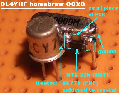 Based on former experiments, a 10 MHz crystal (miniature, but
not SMT) was quickly & carefully soldered to a small signal transistor
(=heater) and a small 22 kOhm-NTC (=resistor with negative temperature
coefficient, a cheap temperature sensor). A PNP transistor with a metal can
enclosure was used, because the transistor's case is connected to the collector,
and the collector will be connected to ground. The crystal's case is also
connected to ground. So the transistor (heater) could be soldered directly
to the crystal. One end of the NTC was also connected to ground. The heart
of this OXCO, which would later be stuffed in foam rubber, is shown in the
photo on the left.
Based on former experiments, a 10 MHz crystal (miniature, but
not SMT) was quickly & carefully soldered to a small signal transistor
(=heater) and a small 22 kOhm-NTC (=resistor with negative temperature
coefficient, a cheap temperature sensor). A PNP transistor with a metal can
enclosure was used, because the transistor's case is connected to the collector,
and the collector will be connected to ground. The crystal's case is also
connected to ground. So the transistor (heater) could be soldered directly
to the crystal. One end of the NTC was also connected to ground. The heart
of this OXCO, which would later be stuffed in foam rubber, is shown in the
photo on the left.
The photo on the right shows the
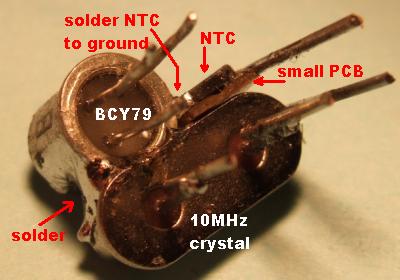 the
bottom view. A small, thin piece of PCB was used to hold the NTC resistor
in place, close to the crystal. If you have an NTC resistor with wire
connections, solder it to the crystal, and use epoxy resin (or similar) to
improve the thermal contact.
the
bottom view. A small, thin piece of PCB was used to hold the NTC resistor
in place, close to the crystal. If you have an NTC resistor with wire
connections, solder it to the crystal, and use epoxy resin (or similar) to
improve the thermal contact.
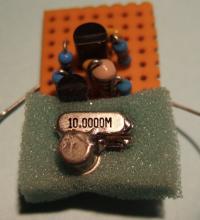 Before plugging this "7-legged bug" into the oscillator
PCB, the bug's legs are sticked through a small block of foam rubber as shown
on the left . A second part of the same size will later be used to insulate
the upper part, so the "heater" (PNP transistor), the NTC, and the crystal
will be completely surrounded by foam rubber (or other thermally and electrically
insulating material). But first we must find the optimum operating temperature
for the crystal.
Before plugging this "7-legged bug" into the oscillator
PCB, the bug's legs are sticked through a small block of foam rubber as shown
on the left . A second part of the same size will later be used to insulate
the upper part, so the "heater" (PNP transistor), the NTC, and the crystal
will be completely surrounded by foam rubber (or other thermally and electrically
insulating material). But first we must find the optimum operating temperature
for the crystal.
In commercially manufactured OCXO's, special crystals are used which have a temperature coefficient of almost zero at at their operating temperature. In other words, there is a temperature range where a small change in temperature does not affect the frequency. Cheap "computer-grade" crystals like the one used here are not designed for such applications, but the usually have at least one point where the temperature coefficient is almost zero. It can be found by experiment: Let the crystal run in a test oscillator, and slowly heat it up with the transistor, and watch the output frequency. This can be done with a "waterfall"-display and a single-sideband shortwave receiver tuned to the oscillator frequency.
But first a note about the "heater" used in the initial experiment: The BCY79 is a small signal transistor with 200 mA max collector current, 1 W max. power dissipation at a case temperature of 45 °C, a max junction temperature of 200°C, and a thermal resistance between junction and case of 150 K/W. If the case reaches 100°C during the heat-up phase, the maximum power dissipation must not exceed (200°C-100°C)/(150K/W)=0.66 Watts. For some safety margin, keep the maximum power dissipation below 0.5 watts, which means Ic<60 mA at 8 volts supply voltage. In the prototype, a 47 kOhm base resistor was used (the transistor had a current gain of 350, which is a typical value).
During the heat-up experiment, the temperature can be (coarsely) measured through the resistance of the NTC. The following table was taken from a datasheet for the 22-kOhm-NTC used here (Epcos C619, 22kOhm at 25°C, R/T characteristics #1008):
| R_ntc / kOhm | 26.7 | 22 | 18.6 | 15.1 | 12.6 | 10.6 | 8.9 | 7.52 | 6.37 | 5.44 | 4.66 | 4.00 | 3.45 |
| Temp. / °C | 20 | 25 | 30 | 35 | 40 | 45 | 50 | 55 | 60 | 65 | 70 | 75 | 80 |
With this table in mind -"don't let the NTC resistance drop below 3.45 kOhm"- the crystal oven was heated for the first time, with the frequency offset being plotted on a waterfall diagram. The result:
The "heater" (PNP transistor at 8 V, 60 mA) was turned on at 20:24, when the temperature was 20°C. During the first minute, the crystal heated up to 47°C (NTC=9.6kOhm). Two narrow, and therefore unusable inversion points can be seen during this time. But more interesting is the flat part of the curve later (near 20:26), when T was between 55 and 60°C (NTC=6.8 kOhm). This seemed to be a good "operating point". In the 3rd minute, heating the crystal up to 65° rose the frequency again (and touching the crystal with the soldering iron made the frequency rise even more.. ouch ! ).
- Note:
- Of course the "heating curve" will be different for other crystals. Make sure there is a flat inversion point (where the temperature coefficient is almost zero) at a temperature *above* the highest operating temperature of your equipment, because it's much easier to heat a crystal instead of cooling it down. On the other hand, the temperature shouldn't be too high (say below 80°C) to avoid stressing the components. If it doesn't work with the 1st crystal from the junk-box, try the 2nd..
Back from the 'homebrew'- to the 'commercial' OCXO
With the complete-homebrew OXCO running stable enough, a test run was made to compare it with the 'commercial' OXCO. Quite disappointing result (though not really a surprice): The 'commercial' OCXO beat the stability of the 'homemade' oscillator by a decade (or even more). So the bandwidth (and 'capture range') of the loop filter for the homebrew oscillator would have been much higher than for the commercial one, so I decided it was time to open the shiny metal box with a dremel-like motor tool - partly for curiosity. The shell was hard to crack, but I finally managed to open it without destroying any vital parts. Here the opened 'commercial' OCXO (before the variap diode was installed to make it 'electrically tuneable' ) :
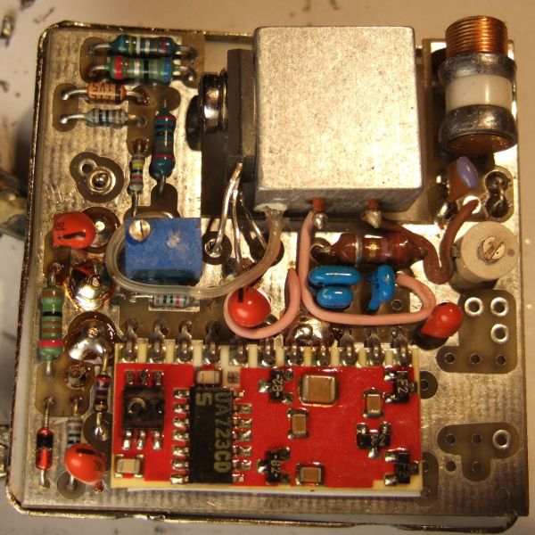
( commercial 10 MHz OCXO, opened with a motor tool)
The crystal sits in a small 'oven' (actually a large piece of aluminium), heated with a transistor on the left. This 'oven' was thermally isolated with a foam-like material which was removed temporarily.
Interestingly there were some unused pads on the PCB (left side on the image above). A nice invitation (*) - a varicap diode from an old UHF TV tuner was quickly installed, using a small coupling capacitor so the overal tuning range was only 5 Hz. The tuning voltage is connected through a 100 kOhm series resistor and some more HF-decoupling to the unused pin (which is in the upper left part of the photo).
- (*) This free space IS actually there to install a varicap diode !
- So if you are lucky you can find a similar OCXO which already has a varicap tuning diode installed.
After installing the UHF varicap diode, the OCXO was reassembled and the housing soldered together again. The varicap was biased at 2.5 Volts, and the trimming capacitor adjusted for 10.00000 MHz again (using the 10 MHz -> 77.5 kHz divider and DCF77 again, as explained in the first chapter). It turned out later that I hardly needed the DCF77 reference, because this oscillator "running free" is accurate enough for my purposes. Locking it permanently to the DCF77 reference may cause more problems due to day/nighttime propagation on longwave; so I leave everything as it is for the moment.
- to be continued ? -
(not really. Years later, when affordable GPS receivers with 1-pulse-per-second 'sync' output
became available, a very stable GPSDO (GPS-disciplined oscillator), using just a PIC and a
surplus commercial 10 MHz VCOCXO was built.
Details, photos, and PIC firmware here ).