
Written for Linux users. Device: STM32F072xB • TCXO 26MHz • Oscillator: MS5351
- NanoVNA-H Topics:
- Firmware
- Calibrate
- Antenna Testing
- Coax Testing
- Connect to Computer for ease of viewing (NanoVNA-Saver Software)
1 Updating the Firmware on Linux
Keeping your NanoVNA-H firmware current improves accuracy, adds features like SD card support, and fixes bugs. These instructions cover updating to the DiSlord firmware build, which is the most actively maintained version for the NanoVNA-H.
Step 1 — Verify Your Oscillator Mode
Before downloading firmware, confirm your oscillator setting. On the device navigate to CONFIG → EXPERT SETTINGS → MORE → MODE and note whether it shows Si5351, MS5351, or SWC5351. Write this down — a firmware update will reset it to the default and you will need to restore it afterward.
The AURSINC NanoVNA-H may use either chip regardless of purchase date. The MODE menu is the definitive way to check without opening the device.
Step 2 — Install dfu-util
Open a terminal on your Linux machine and install the flashing utility:
Verify it installed correctly:
Version 0.9 or later is sufficient.
Step 3 — Download the Firmware
Create a working folder and download the correct firmware file. For the NanoVNA-H (not H4), you want the .bin file — it covers both Si5351 and MS5351 hardware:
Verify the download integrity with the SHA256 checksum:
The result should match exactly:
f0c4d310e960420fa3b5ed485a52285e6b280d1a3535c3992ac824499c1de56f
For versions newer than v1.2.46 OR for NanoVNA.H4, files and hashes can be found at DiSlord Releases
Step 4 — Enter DFU Mode on the NanoVNA
With the device powered on and not yet connected to USB, navigate to:
CONFIG → DFU → RESET AND ENTER DFU
The screen will go blank or white — this is normal. Now connect the NanoVNA to your Linux machine via USB.
Step 5 — Verify Linux Detects the Device
You should see something like:
If you get a permissions error when flashing, fix it with:
Or simply prefix the flash command with sudo.
Step 6 — Flash the Firmware
The device will reboot automatically when done. If it does not reboot after 10 seconds, power-cycle it.
Step 7 — Restore Your Oscillator Mode Setting
Firmware updates reset the MODE setting to the default (Si5351). You must restore it to your correct chip immediately after flashing, before taking any measurements or calibrating.
Navigate to CONFIG → EXPERT SETTINGS → MORE → MODE and set it back to the value you noted in Step 1.
lsusb will show DFU mode. Reflash with the correct file.
2 Calibrating the NanoVNA-H
Calibration corrects for the small errors introduced by cables, connectors, and the device itself. It must be performed every time you change the frequency range, after a firmware update, or any time you want accurate measurements. Calibration is only valid for the frequency range over which it was performed.
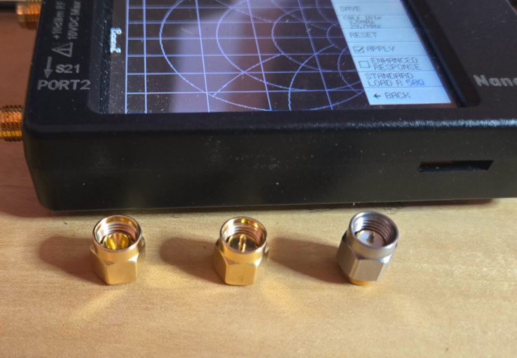
Your Calibration Kit
Your kit contains three standards used for calibration:
OPEN — An open SMA connector with nothing inside. Represents an open circuit.
SHORT — A metal slug that shorts the center pin to the outer shell. Represents a short circuit.
LOAD — Contains a 50Ω resistor. This is your dummy load terminator. Represents a perfect 50Ω match.
Step 1 — Set the Frequency Range
Tap STIMULUS on the main menu.
- Tap START → enter your start frequency in Hz, then tap x1. (Or enter the number and tap M for MHz — e.g., enter 3.5 then tap M for 3.5 MHz.)
- Tap STOP → enter your stop frequency the same way.
Common ranges for amateur HF work:
80m–10m antenna testing: Start 3.5 MHz, Stop 29.7 MHz
80m–6m general coverage: Start 3.5 MHz, Stop 54 MHz
Full HF range: Start 1 MHz, Stop 30 MHz
Step 2 — Set Up the Display
For antenna and SWR work, simplify the display to just one S11 trace:
- Tap DISPLAY → TRACE and turn off all traces except TRACE 0 (S11).
- Tap DISPLAY → FORMAT S11 REFL and select LOGMAG for return loss in dB, or SWR if you prefer direct SWR readings.
Step 3 — Run the Calibration Sequence
Tap CALIBRATE → CALIBRATE to begin. Perform each step in order:
- Connect the OPEN to Port 1 → tap OPEN → wait for sweep to complete.
- Replace with the SHORT → tap SHORT → wait for sweep to complete.
- Replace with the LOAD (50Ω dummy load) → tap LOAD → wait for sweep to complete.
- Tap DONE.
- Tap SAVE and choose a memory slot (0–4) to store the calibration.
Step 4 — Recall a Saved Calibration
To load a previously saved calibration, tap RECALL from the main menu and select the appropriate slot. The device will display the calibration range that was saved in that slot.
3 Testing an Antenna with the NanoVNA-H
The NanoVNA measures how well your antenna system matches 50Ω across a range of frequencies. A good match means more of your transmitter's power reaches the antenna (and the air) rather than being reflected back.
Before You Test: Important Setup Notes
Test outdoors in the final operating position. This is the single most important rule. Nearby metal objects, building wiring, and walls all interact with your antenna's near field and will give you misleading readings indoors. Even moving the antenna a few feet can change the results significantly.
Calibrate for your test range with the coax you will use during testing connected, if possible. Cable losses and phase shift affect readings when calibration was done at the port but measurement is at the other end of a long feedline.
Using a 9:1 or 4:1 UNUN: A 9:1 UNUN transforms the impedance by a factor of 9, designed to match a high-impedance antenna (like a long wire or end-fed) down to approximately 50Ω. A 4:1 UNUN transforms by a factor of 4, designed to match around 200Ω down to approximately 50Ω. Your NanoVNA readings through the UNUN reflect the combined system of the UNUN plus the antenna — not the antenna alone.
Step 1 — Prepare the NanoVNA
- Set your sweep range to cover the bands you want to test (see Section 2, Step 1).
- Recall your saved calibration for that range (RECALL → slot number).
- Set the display to LOGMAG (return loss in dB) or SWR — both are useful. LogMag shows dips clearly; SWR gives the familiar 1:1, 2:1, 3:1 values.
Step 2 — Connect and Observe
- Connect your antenna feedline to Port 1 of the NanoVNA.
- Observe the trace across the sweep range.
- Place a marker at any dip (tap MARKER → MARKER 1 then tap the dip on screen) to read the exact frequency and value.
Reading the Results
LogMag (Return Loss) view: Deeper dips = better match at that frequency.
Better than -10 dB — Acceptable match (SWR ≈ 2:1 or better)
Better than -14 dB — Good match (SWR ≈ 1.5:1)
Better than -20 dB — Excellent match (SWR ≈ 1.2:1)
SWR view: Lower is better. Most transceivers are happy with SWR below 2:1. An internal tuner can usually handle up to 3:1. Higher than 3:1 typically requires an external tuner.
Smith Chart view: The center of the chart represents a perfect 50Ω match. A trace clustered near the center indicates a well-matched antenna system. A trace riding around the outer edge indicates a highly reactive (poorly matched) load.
Multiband Antenna Notes
A multiband antenna (such as one covering 80m through 10m) should show a dip in the trace near the resonant frequency of each band. These dips may not all be equally deep — that is normal. An antenna tuner handles bands where the SWR is elevated.
If you see no dips at all, or the trace is a nearly flat line at a high SWR value, check:
- That the antenna is connected and the feedline is intact.
- That your calibration was saved and recalled correctly.
- That the UNUN connections are solid.
- That the antenna is outdoors and away from metal objects.
AA4TE • NanoVNA-H Guide • Firmware v1.2.46 • Last updated 2026
Device: AURSINC NanoVNA-H • STM32F072xB • TCXO 26MHz • MS5351
Written with the assistance of Claude by Anthropic