
Layout for cutting pieces from stove pipe.
An Experiment with a Rocket Stove - page 10a
Previously, I tried making an "improved" rocket stove from a single 8"
diameter by 24" long, black vent pipe. This time I wanted to make a more
efficient stove based on the original concept of using a small diameter chimney.
An outer cover acts as a support for the cook pot. This design, as in the other
two, is made to hold up to a 10" diameter cook pot. As before, I used steel
"pop-rivets" as fasteners, but screws or spot welding would also work.
The legs, baffle, pot supports, heat chamber/ chimney, and outer cover were all
made from a single 8" diameter x 24" stove pipe. The outer cover uses about
one-half of the material. It stands about 10 1/2" tall. While the design I settled on
is more time-consuming to build, the idea was for the smaller heat chamber/chimney to make the stove more efficient in wood use, and more stable, while not
using any more sheet metal.
This page shows details of how I constructed the stove that I tested on the
rocketstove10.htm page.
Layout for cutting pieces from stove pipe.
First, cut out the various pieces from the 24 ga., 8" diameter x 24" long black
vent pipe (source-Menards, approx. $7). I used 1/8" diameter by 1/4" long steel
pop rivets for fasteners.
Cut slits in outer cover, fuel inlet, and chimney. Outer cover slits are 2" long at
the top, 1/2" long at the bottom where the cover touches the fuel/air
separator, and 3/8" long around the rest of the base. Cut 3/4" long slits around
the top of the chimney, and after cutting out the 1" radius half-circle from the
edge of the fuel inlet, cut 1" long slits around that edge (they will be bent
upwards when the stove is finished).
Cut the opening for the heat chamber, 4" high by 3 1/8" long and fold outward to
make a 4" wide opening.
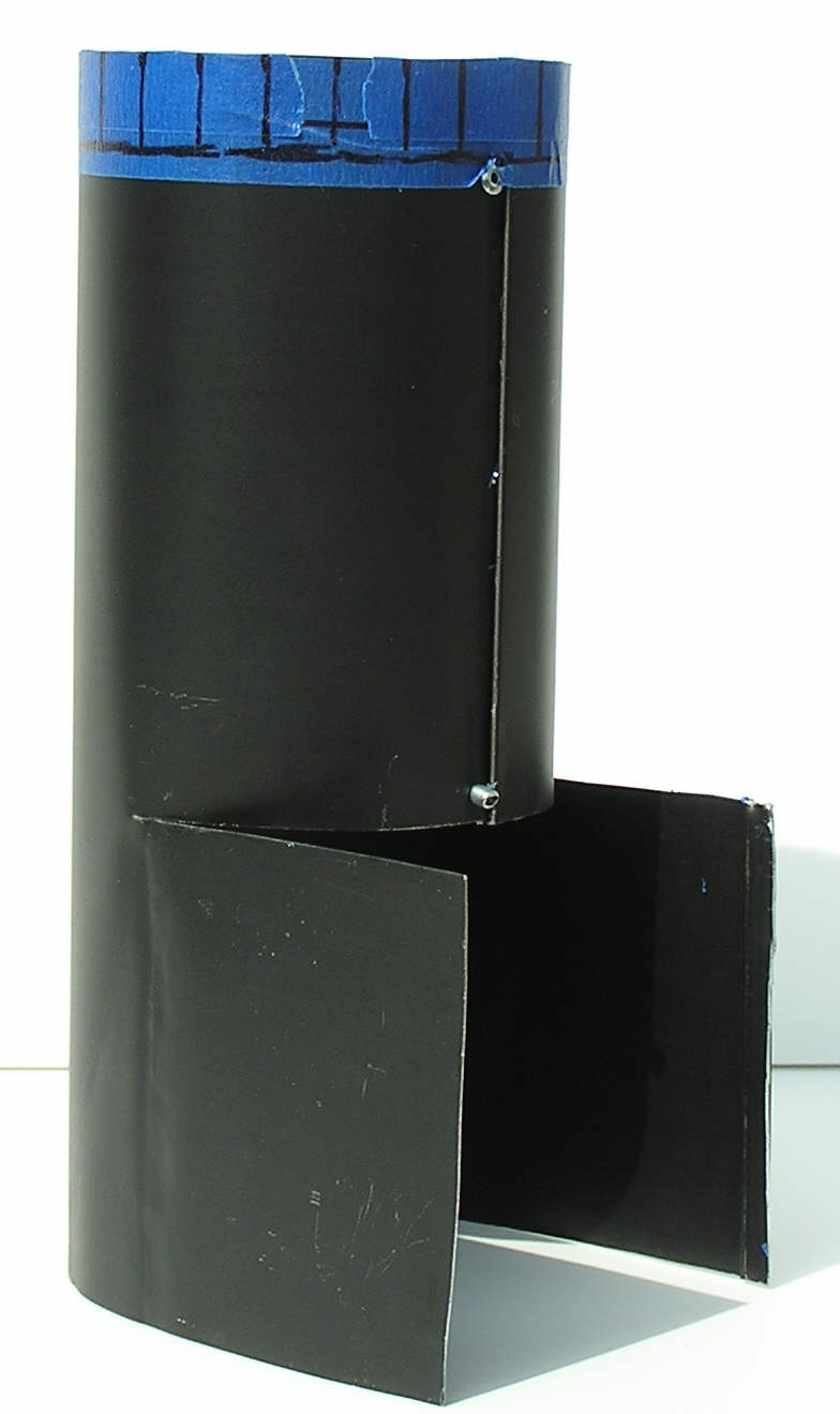
Pop-rivet the top and bottom of the chimney to hold the chimney closed (about 1"
down from the chimney top, 1/4" up from the bottom).
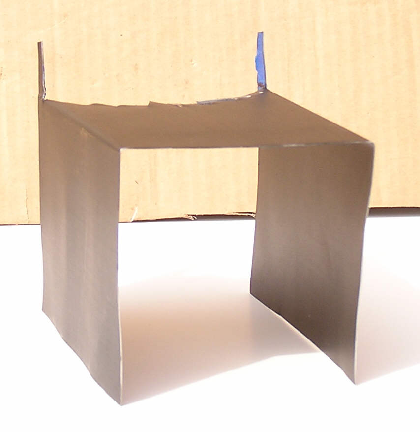
Bend the ends of the pot supports in
opposite directions so the supports are 2" long, to make up the difference
in diameter between the 4" chimney and 8" outer cover.
Drill 1/8" diameter holes in pot support ends for steel pop rivets (two on
one side, and one, centered, on the other).
Push the fuel inlet into the heat chamber so the slits are inside. Set it on the
fuel/air separator, so that there is about 2 3/4" from the edge of the separator
to the back of the heat chamber. The folded edge of the separator should be
inside the stove. Pop-rivet the 3 pieces together on each side about 1" from the
bottom. Cut two slits, 1" long by 1 1/2" wide in bottom of fire chamber, and
fold outward at 90 degrees (lets in a little extra air when ashes start filling
the bottom).
Turn the chimney upside down on a flat surface, set the four pot supports around
the chimney and mark the holes (using the holes in the pot supports as a guide;
two hole side of the support) on the chimney for drilling. Pop-rivet the four
pot supports to the chimney, from the inside. The outside hole on the
supports will attach to the outer cover. The assy. should look like the right picture in the second row.
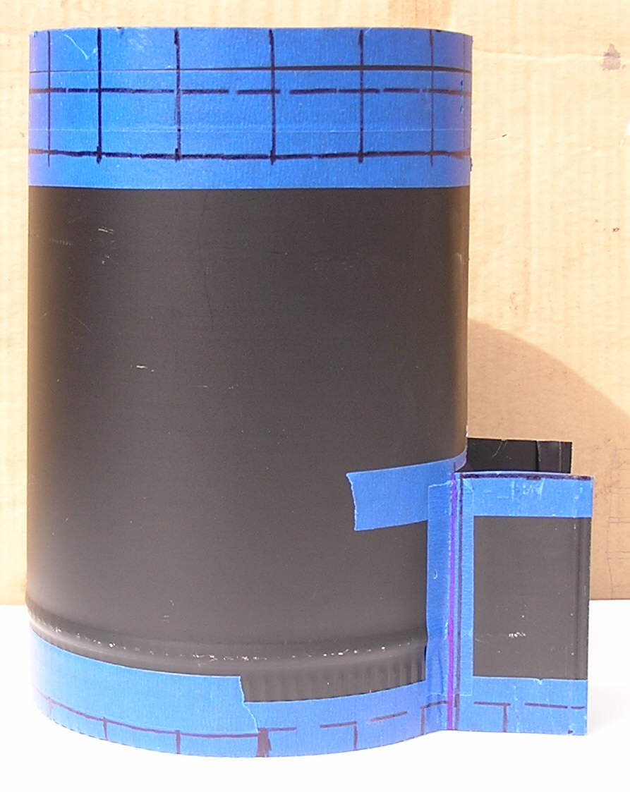
Mark and cut the bottom of the outer cover to form two 4 1/2" high by 2 3/8"
long flaps. Bend them outward to form a 4 1/8" wide opening to fit around the
inner assy. Bend the 2" long top flaps outward, and then bend the outer 1"
upwards to accommodate a 10 cook pot. At the base, bend the 1/2" and 3/8" long
flaps outward. I put two pop-rivets at the seam, just to be safe.
Slide the outer cover down over the inner assy. and pop-rivet it about 1" from
the bottom on each side of the fuel inlet. The rivets should go into the air
passage, not the fuel inlet. Pop-rivet the outer cover to the fuel/air baffle at
the base also (rivet from the bottom side).
The stove should sit level. If not, the 3/8" long flaps around the base can be bent up or
down a little as needed.
Bend the top flaps of the chimney outward at about a 45 degree angle.
Turn the stove upside down and bend the flaps of the fuel inlet down at a right
angle, against the side of the chimney with a large flat-blade screwdriver.
File or sandpaper any sharp edges, and remove any metal "slivers" left from the
cutting process.
The stove should look like the right picture in the third row.

![]()

Fuel inlet (2 views), Fuel/air separator, heat chamber/chimney, assembled fuel
inlet& heat chamber/chimney.


Pot supports, Assembled pot supports, fuel/air separator & fire chamber/chimney.
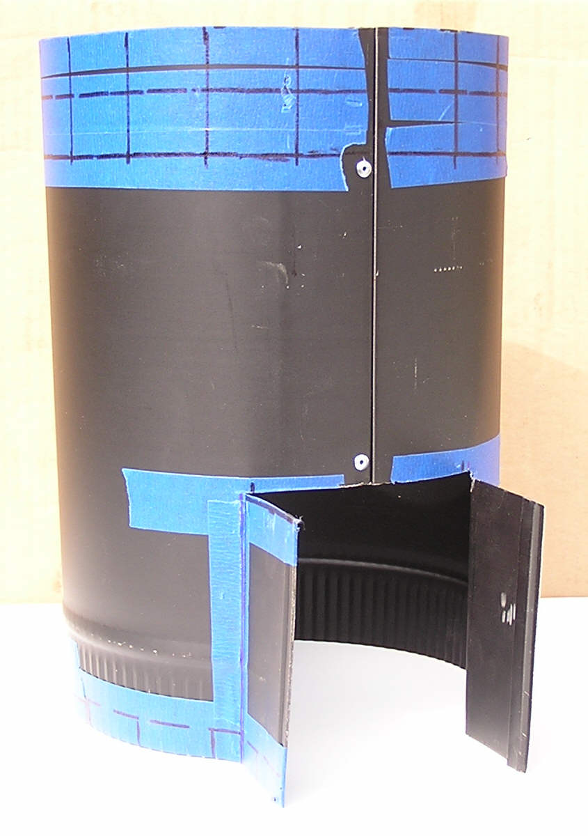


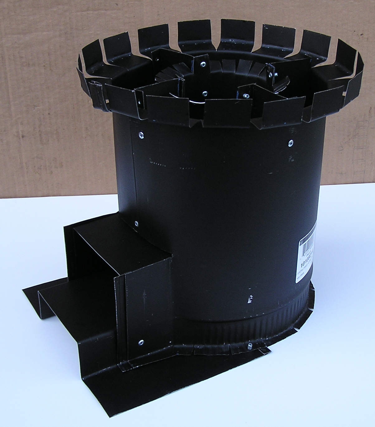
Outer cover (2 views), Outer cover on inner section, top and side views of
completed stove.

Stove with an added 4" high skirt, made from aluminum flashing. It can help the
performance, especially when it's windy. At that point, the stove temperature is
low enough not to melt aluminum. (The flashing was actually 5" x 10" diameter.
One inch long slits were cut at the bottom of the skirt and folded inward at 90
degrees to cover the spaces between the flaps on the top of the stove, giving a
final height of 4".)
From my testing I came up with a general guide for minimizing smoke
here.
L.B.