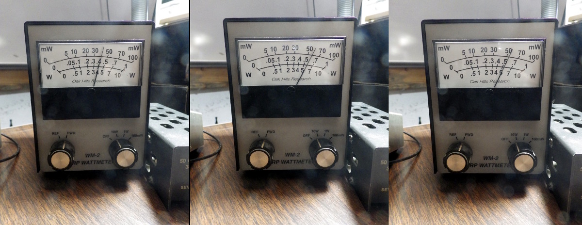
Power for 15, 30, and 40 meter bands.
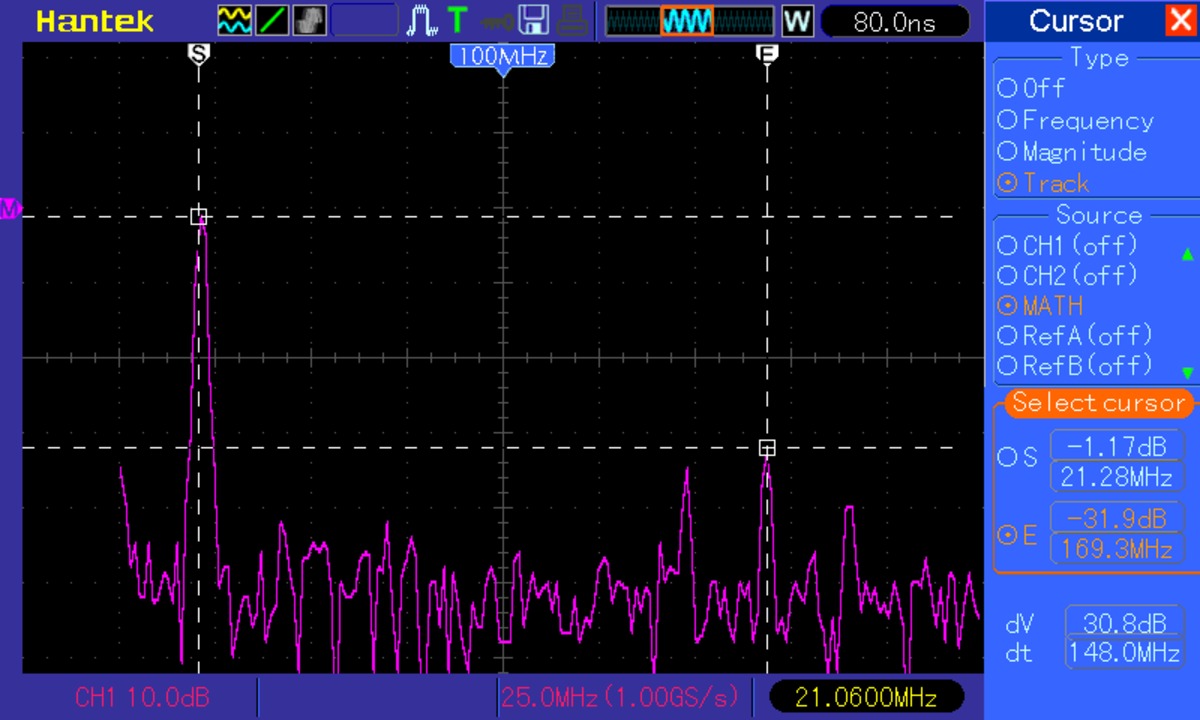
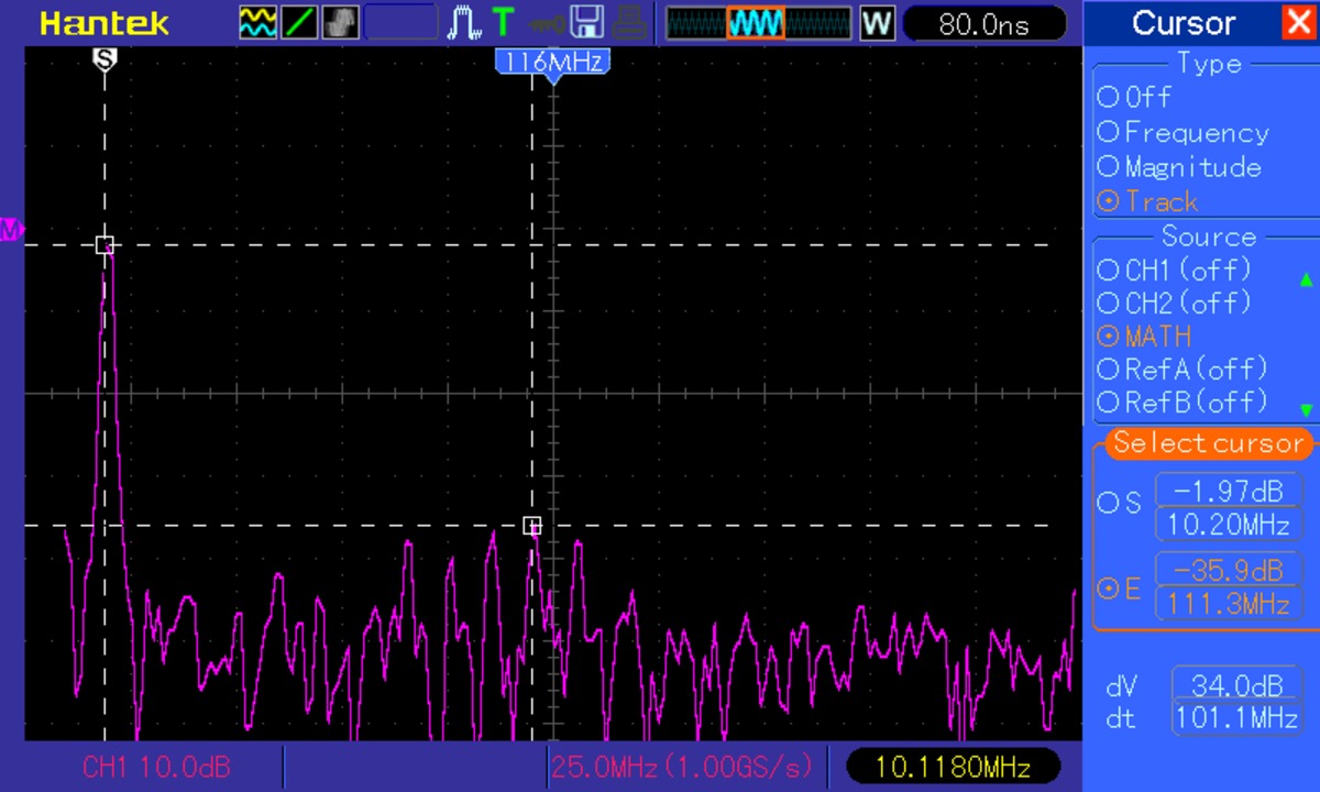
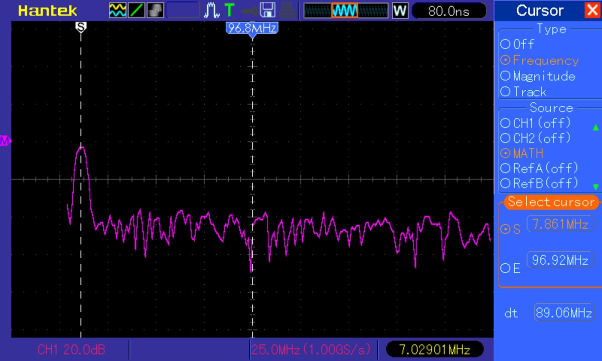
Ok, now on to test the filters with my new FFT capable oscilloscope. Scope outputs are below. These tests were not conducted with any sort of calibrated sampler, so the db values are only relative to one another. First test is 15 meters, where the highest harmonic is way up at 170Mhz, and is 30db down. 30 meters is much the same, with spurious outputs only appearing up near 100Mhz and is 34db down. 40 meters has... nothing at all. No harmonics coming out above what I can detect with the FFT.
Receiver testing
These are all the transmitter tests I have completed. Receiver testing was done with an Elecraft XG1 test oscillator. The XG1 is a precision 7.040Mhz crystal oscillator with a 1uV output. By using the true RMS meter to measure the audio amplifier output with the XG1 on and off, and calculation can be made that results in the noise floor of the receiver.