
Rig Control via Spectrum Lab
Contents
- Transceiver- and PTT control interfaces, CAT control (CI-V)
- Rig control / audio input from certain Icom radios via LAN or WLAN
Transceiver- and PTT control interfaces, CAT control (CI-V)
This item in the Setup dialog is used to define the COM port number where
a "RX/TX" (=PTT) line and other control signals can be connected.
Since Version 2.94, Spectrum Lab can also use the 'Transceiver Interface'
to read 'Scope waveform data' from certain Icom radios as explained later.
In the good old days, there was a simple 'D-Sub' 9-pin male connector
at the backside of each PC. It was very reliable, easy to use,
required no fancy driver installation, and looked as shown at the
end of this chapter.
These days, serial ports have almost completely been replaced by USB.
But from a software's point of view, many of those "controllable rigs"
can still be accessed like 'COM ports' (if you got the required drivers
running properly, which can be cumbersome under "Windows 10" if the hardware
manufacturer doesn't supply a signed driver).
Regardless if the transceiver uses a 'real' serial port,
a camouflaged USB/serial port adapter, a USB interface chip that "looks like
a COM port" for CAT control to the application, or even LAN/WLAN/UDP (as used
by certain Icom transceivers), this document applies to any of them.
Some radios (like recent Icom rigs) can use the same USB port for
audio (in/out), CAT control (computer aided transceiver or tuning)
/ "CI-V" (Icom's proprietary CAT protocol), etc.
If not used as normal serial interface lines, some of the
serial port pins
can be used as discrete switching signals.
These functions are selected on the 'TRX Interface' panel.
Note the difference between the 'Port for PTT control' (left side,
not required for modern rigs where PTT control and keying can
be done via CI-V, without abusing certain lines of an RS-232 port):
Serial port for PTT control and keying
Even modern rigs with built-in USB <-> UART serial port adapter, which can control the PTT though CAT / CI-V commands still support (emulate) the traditional method of keying the transmitter as described here.-
PTT Control:
The hardware required to use this feature is exactly the same as for many 'digimode' software packages. For example, the RTS line of the serial interface can be set HIGH during transmit and LOW during receive. The signal actually used can be selected on this control panel. There are some interpreter commands to access this port, too. Alternatively (if there's no free COM port), consider using a pilot tone for PTT control. Last not least, the PTT of newer Icom radios (e.g. IC-7300, IC-9700) can be controlled via CI-V (CAT) so their USB interface can also key the transmitter, without using one of an emulated RTS or DTR line. In other words: The 'Radio Control Port' decribed further below can sometimes also be used to switch between transmit and receive.
-
CW Keying:
Will be used to generate a slow CW keying signal. -
Alert Bell:
This output can be driven by the Spectrum Alert function. A low signal means "no alert" (bell off), a high signal means "ALERT !" (bell should ring, warning light flashing etc). -
use SmallPort driver to access I/O ports
(removed, because either direct I/O port access or the "smallport" utility caused severe problems under Win XP, and most likely under any later version of windows) -
PTT pilot tone (frequency)
Can be used for PTT switching through a weak pilot tone generated by the soundcard. This is an alternative to control a transmitter if your PC doesn't have a free COM port for this purpose. Whenever the transmitter shall be ON ("sending"), a pilot tone with the specified frequency is added to the output audio signal for the soundcard (approx. 20 dB below the max. output level, added to the signal at label "L5" in the circuit). Use a simple PLL tone decoder like the LM567 or similar to detect the pilot tone, and convert it into a switching signal. Note: The LM567 is marked as 'obsolete part' but it's still easy to find, cheap, and easy to use.
To disable the PTT pilot tone, set the frequency to zero (the default state). Beware to place the pilot tone outside of the transmitter's frequency range, but keep it below the half sampling rate: For example, use 5000 Hz is about the maximum if the soundcard runs at 11025 samples/second.
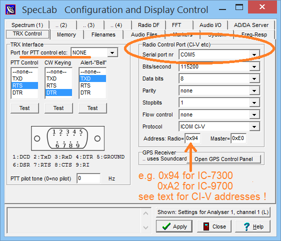
Remote rig control (CAT, CI-V)
The group "Radio Control Port" can be used if Spectrum Lab shall be used to remotely control a suitable receiver (a "real radio"). Details can be found in the chapter "Interpreter commands for Remote Control" (you can use SL's "programmable buttons" to switch mode, filter bandwidth,etc). This port is also used to pull 'spectrum scope' data from modern rigs like IC-7300 and IC-9700, and for the OpenWebRX-alike web server when connected to a 'real' radio instead of an SDR with broadband I/Q output.The parameters for this port are:
-
Port/Address (in older versions: Serial port number)
In most cases, pick the 'COM port number' from this (also applies to radios controlled via USB with a virtual COM port). Only a few modern radios (like IC-9700 and IC-705) can be remotely controlled via LAN or WLAN as explained in a separate document, e.g. as pseudo-URL udp://IC-705:50001 .
Note: Don't use the same port as for the PTT control (set the PTT control port to "none" if your PC only has one serial port, or if the PTT shall be controlled via CAT / CI-V through the radio control port).- For Icom users:
- If you also have difficulties finding the ever-changing COM port number
currently used by your IC-7300 or IC-9700 or whatever, open the windows device
manager (e.g. from the command line: devmgmt.msc),
and expand the list of 'Ports (COM & LPT)'. As of 2020, these radios
appeared as 'Silicon Labs CP210x USB to UART Bridge (COMx)' there.
Of course your mileage (the 'x') will vary. Try the COM port
shown in parenthesis, e.g. 'COM8'.
To avoid this hassle ("which of those COM ports leads to
which of my radios ?") over and over again,
always plug the radio into the same USB port, and if
you're lucky, the port number doesn't change anymore.
If there's more than one ''Silicon Labs CP210x USB to UART Bridge' (or whatever the name will be next) listed in the Device Manager, pull out the USB cable and watch which of those COM ports disappears. Just turning off the radio doesn't always help, because e.g. the IC-7300's USB <-> UART converter chip is USB-powered (keeps running even if the radio is turned off).
In contrast to the above, an IC-705, when connected to the PC via *USB* (not WLAN), appeared as 'Serielles USB-Gerät (COM8)' plus a 'Serielles USB-Gerät (COM9)' (on Windows 10 System with German UI). Which of those two 'COM' ports is for the transceiver remote control (CI-V), and which of them is the 'PTT' / keying port (or the port for the 'GPS output') ?
Again, the annoying solution was 'trial-and-error'.
-
Bits/second
Some old ICOM radios used 1200 bit/second, others use 9600 bit/second.
Modern rigs need 115200 bit/second to retrieve 'spectrum scope' data via CI-V.
Check your radio's manual ! -
Data bits
Set this parameter to "8" which works for 99% of all cases ;-) -
Parity
Set this parameter to "none" for ICOM's CI-V protocol -
Stopbits
Usually set to "1". Some radio's manuals recommend two stopbits. -
Flow control
Set this to "none", because most radios use neither RTS/CTS (hardware flow control) nor XON/XOFF (software flow control) -
Protocol
Set this to "ICOM CI-V", or different (one fine day). The selection "none / ASCII-Text" means you can only send ASCII strings to the radio through an interpreter command, but there will not be any manufacturer-specific translation, message acknowledge etc. -
Address of the Radio (Icom: "CI-V Address")
This hexadecimal value (with "0x" prefix) must match the "CI-V Address" of the radio. You will find the default value in your radio's manual. Here are values for a few ICOM radios:
Model IC-9700 IC-7300 IC-7610 IC-735 IC-751A IC-725 IC-705 IC-905 IC-706 IC-706MkII IC-706MkII-G IC-756 ...
Address 0xA2 0x94 0x9A 0x04 0x1C 0x28 0xA4 0xAC 0x48 0x4E 0x58 0x50 ...
Note that for the "older" three HF radios, the frequency is sent with 8 digits only, while for most "newer" radios 10 digits are exchanged. So if you set the CI-V address of your IC-706 to 0x04 in its menu, SpecLab will think it's an old IC-735 and only send 8 digits (which fails if the frequency is above 99 MHz). So better keep the radio's default address, and select that address in Spectrum Lab. This even applies to radios connected via LAN or WLAN.
-
Master Address (for CI-V protocol)
Usually set to 0xE0... at least this is what ICOM uses in their own examples.
- Note for users of Icom radios:
- An Icom IC-7300's serial port emulator appeared as
'Silicon Labs CP210x USB to UART Brigde (COM6)'
in the windows system control.
But of course your mileage will vary !
When plugging the USB cable into another port, windows
assigns a different COM port number per default.
The "soundcard" emulated by the IC-7300, IC-9700, and possibly similar Icom radios was an anonymous "USB Audio CODEC".
Important note (quoted from Icom's USB driver installation guide, Before connecting to a PC):
The USB driver is not supported by the automatic
recognition system, so NEVER connect the USB cable
between the radio and the PC until AFTER the USB
driver has been installed.
(SL's author could not confirm this, but you've been advised.)
Displaying Icom's broadband spectrum scope in Spectrum Lab's main window,
Serial port duplicator using com0com.
Serial port pins
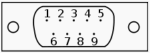
9-pole "D-sub" connector, male, "DTE" connector side
| Pin Number | Signal Name | Direction (at the "DTE" side) | In SL, usable as |
1 |
DCD |
input |
|
2 |
TxD |
output |
PTT or slow keying, |
3 |
RxD |
input |
serial data from radio |
4 |
DTR |
output |
PTT or slow keying |
5 |
GND |
signal ground |
|
6 |
DSR |
input |
|
7 |
RTS |
output |
PTT or slow keying |
8 |
CTS |
input |
|
9 |
RI |
input |
Remote Control Functions / Commands (in the interpreter),
Synchronizing SpecLab with a radio's VFO via CAT (works both ways, from SL to the radio, and from radio's "VFO knob" to SL)
back to top
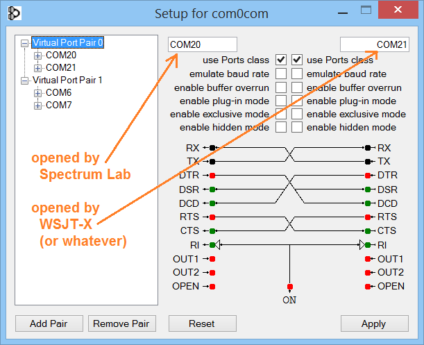
Serial port duplicator using com0com (virtual Null-modem cable)
A common annoyance with serial ports (in this case, for remotely controlling a radio) is that if one application opens the port, no other application can use the same serial port. Even if windows would allow applications to share the same 'COM' port, there would be collisions if two applications try to transmit commands to the radio at the same time. Data from the radio to the controlling application(s) could simply be duplicated, but applications that "think" they are directly controlling the radio may be irritated by responses for commands they didn't send (similar as the notorious "Rig Control Error" in WSJT-X when rotating the radio's VFO knob..). So there must be some kind of synchronisation if two (or more) applications want to 'talk to' the radio at the same time.The solution is: Only Spectrum Lab talks 'directly' to the radio is described in this chapter. It can be configured to accept commands for 3rd party applications (e.g. WSJT-X), and will send responses back to the 3rd party application just as if the application had 'direct control' over the radio on a different COM port number. In Spectrum Lab, those are the client ports explained further below. By the way, there is a similar concept also in the author's Remote CW Keyer (the 'Additional COM Ports' in CW Keyer can be used for almost anything, including letting 3rd party applications control the radio as if it was connected locally via USB or serial port).
First of all, install the proper version of com0com with a signed driver for windows from https://sourceforge.net/projects/com0com/ (don't throw away your money, com0com is free, don't invest $$$ for similar products. A simple "Null-modem emulator" is all we need for this purpose.).
After installation, open com0com's control panel (it's in the "Programs" menu under "com0com".."Setup") and create a pair of COM ports that don't exist on your system yet. In the example below, these were "COM20" and "COM21". Data sent into this 'virtual NULL-modem cable' from one end arrive at the other, and vice versa.
Options .. System Settings .. Tx/Rx Interface Settings
Right next to the 'Radio Control' tab (which configures the port that connects 'to the radio' from SL's point of view), enter tab Client #1 (or Client #2 if you need another port for another application).
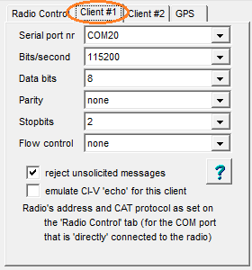
- Reject unsolicited messages
- Some amateur radio software (e.g. WSJT-X when using Hamlib in 2018)
get confused when receiving anything from the radio that they don't understand.
Some even stop working, or bug the operator with message boxes showing
"Rig control error" (we'll get back to that later). If you suspect
a problem like this, check this option ('reject unsolicited messages').
Other software (like Icom's RS-BA1) expect to receive everything from the radio, including VFO frequency reports, spectrum scope data, etc, even without wastefully polling them every few milliseconds. The latter are called 'unsolicited' throughout this document because the radio sends such messages 'without being asked for'.
RS-BA1, Win4Icom, HRD, and similar advanced software will not work (over one of SL's client ports) if the option 'reject unsolicited messages' is set. Thus the default setting is unchecked.
- Emulate CI-V 'echo' for this client
- Some clients (software that expects to talk 'directly'
to an Icom radio) expect an immediate 'echo' because when CI-V was still
a 'single-wire bus' (not USB), data sent on the PC's TxD signal
immediately returned on RxD.
To detect collisions, clients listened to their own transmission on RxD,
and if the received 'echo' wasn't equal to the transmitted message,
threw an error / message box with "Ding-dong ! Rig control error !".
back to top
Rig control / audio input from certain Icom radios via LAN or WLAN
More recent Icom radios fortunately allow sending / receiving control command, audio, and spectrum 'waveform' data via LAN (e.g. IC-9700) or even WLAN (IC-705), so the days of ever-changing (virtual) "COM port numbers", non-functional USB drivers, and similar will hopefully be over one fine day.At least for the Icom radios mentioned above (personally used by SL's author), it was quite easy to modify the exising CI-V code to use LAN (in fact Ethernet) or WLAN (Wireless Lan using the same Windows Socket Services as for LAN) instead of physical or virtual (USB-based) "COM ports", because on the application layer, both ("USB"/COM or LAN,WLAN) use Icom's CI-V protocol internally for almost anything.
To use Spectrum Lab directly with one of the LAN / WLAN equipped Icom radios, first establish a connection via LAN / WLAN as described in the extra document about Icom radios with LAN or WLAN.
Last modified : 2025-07-12
Benötigen Sie eine deutsche Übersetzung ? Vielleicht hilft dieser Übersetzer (Google Translate) !
Avez-vous besoin d'une traduction en français ? Peut-être que ce traducteur vous aidera !