| LEARNING OBJECTIVES AND NOTES
|
|
| AC circuits 2 |
|
Recall that for a resistor, the potential difference and current are in phase.
Recall that current lags potential difference by 90°in an inductor and that current leads by 90° in a capacitor.
In the last lesson
we looked at two voltages on the same wire and established there can be
a phase shift between the two varying from 0 to 360 degrees.
We can also look at the phase shift between voltage and current in the same circuit.
If we set up a circuit with a resistor there is no phase shift between the current and voltage.(P.D.). The peak in voltage is at the same point as the peak in current.
If we set up a circuit with a capacitor we can see that there is a 90o phase shift between voltage (P.D.) and current. The current is 90o in advance of the voltage.
One way to remember this
is to think of ICE where C stands for capacitor, E for voltage and I
for current. In ICE the current(I) leads the voltage (E)
If we set up a circuit with an inductor there is also a 90o phase shift between voltage (P.D.) and current, but this time the current is 90o behind the voltage.
One way to remember this is to
think of ELI where L stands for inductance, E for voltage and I for
current. In ELI the voltage (E)leads the current(I).
So to remember the phase difference in capacitors and inductors remember:
ELI the ICE man
|
|
Recall
that the term ‘reactance’ describes the opposition to current flow in a
purely inductive or capacitive circuit where the phase difference
between V and I is 90°.
Reactance is the resistance to alternating current shown by an inductor
or a capacitor. Reactance ignores any DC resistance in the circuit.
A circuit with a
capacitor will show some opposition to alternating current, just as a resistor shows
resistance to current. This is called capacitive reactance
and it's value will depend on the size of the capacitor and the
frequency. Reactance is measured in ohms and is given by the equation:

where
f=frequency in hertz
C=capacitance in farads
Xc=capacitive reactance in ohms
Pi=3.14
The
two examples show that increasing the frequency in a capacitor
decreases the reactance. Also increasing the capacitance decreases the
reactance.
Remember that capacitors block DC but allow AC.
Inductors block AC but allow DC.
A circuit with inductance will show some opposition to alternating current, just as a resistor shows
resistance to current. This is called inductive reactance
and it's value will depend on the size of the inductor and the
frequency. Inductive reactance is measured in ohms and is given by the equation:

where
f=frequency in hertz
C=capacitance in farads
XL=inductive reactance in ohms
Pye=3.14
Examples
3 and 4 show that increasing the frequency in an inductor
increases the inductive reactance. Also increasing the inductance
increases the reactance.
|
|
Example 1
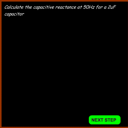
Example 2
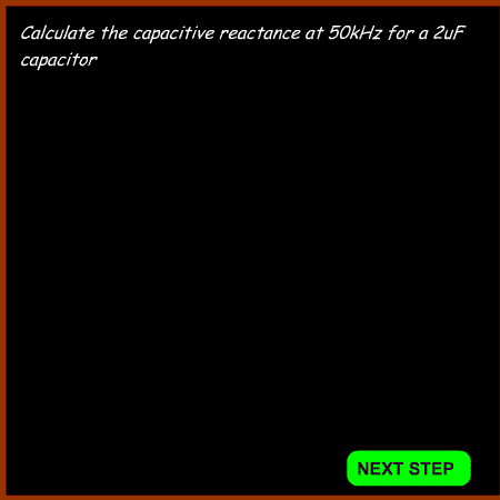
Example 3
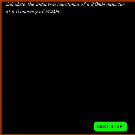
Example 4
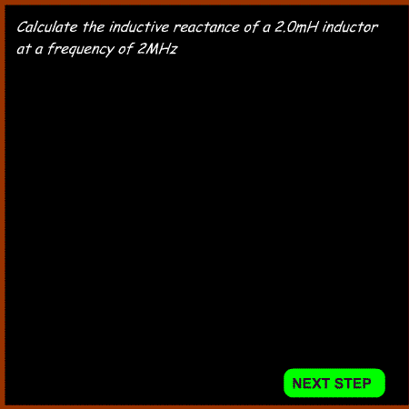
|
Understand that impedance is a combination of resistance and reactance
and apply the formulae for impedance and current in a series CR or LR
circuit.
The term impedance
is a combination of resistance and reactance in an AC circuit. The reactance can be either inductive or capacitive.or
both. Unfortunately you can't just add up the resistance and reactance
to get the impedance.
Impedance is measured in ohms and given the symbol Z. This is the formula used:

Where
Z=impedance in Ohms
R=DC resistance
X=reactance
Once the impedance is known , the current can be calculated from:
I=V/Z
where I = current in Amps
V = voltage
Z=impedance in Ohms
The current in an inductive circuit can be calculated from:
I=V/Z
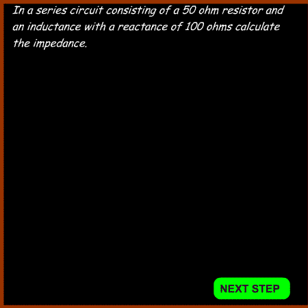
In example 5 if the AC voltage is 100V
I=V/Z = 100/112 = 0.89 amps
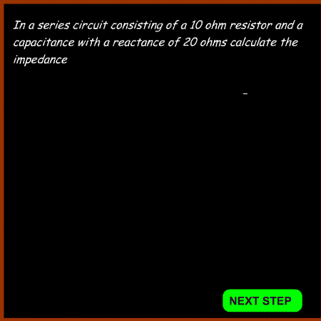
In example 6 if the AC voltage is 100V
I=V/Z = 100/23.4 = 4.3 amps
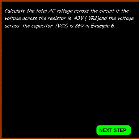
For calculating the voltage across a series resistor and either a capacitor or an inductor. The following formula is used:

Where VT = total voltage
VR2 = Voltage across the resistor
VC2 = voltage across the capacitor
VL2 = voltage across the inductor
|
Example 5
Example 6
Example 7
|
Understand the use of capacitors for AC coupling (DC blocking) and decoupling AC signals (including RF bypass) to ground.
AC coupling (DC blocking)
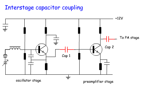
In many circuits there is a need to allow AC to pass to the next stage,
but preventing any DC getting to the next stage. The answer to the
problem is to link the two stages with an appropriate capacitor. The AC
will "pass through", but the DC will be blocked. Remember that "pass
through" is not quite correct. What happens is a surplus of electrons
build up on one side and then on the other side when the AC changes
polarity. In this case the reactance of the capacitor needs to be
calculated to have a low impedance at the design frequency.
The circuit opposite shows a crystal oscillator stage linked to a
preamp via Cap 1. Cap 2 takes the output from the preamp and feeds it
to the PA stage.
|
 |
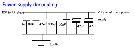
Decoupling
In many circuits it is important to remove AC from a line. This can be
achieved by connecting a capacitor from the positive line to the negative rail /
earth line of the circuit. This will prevent unwanted AC entering other
parts of the circuit via the power line. This is particularly important
in the PA stages of transmitters where RF could be fed back to the
input stage causing the PA to act as an oscillator rather than an
amplifier.
This circuit opposite(from the AQRP club 20W amplifier) uses an
extensive range of decoupling capacitors each covering a different
range of the RF spectrum to keep any RF from entering the 12 volt
supply line.
You will also see some decoupling capacitors on the circuit above. |
 |

