| LEARNING OBJECTIVES and Notes |
|
| Tuned Circuits 1 |
|
Understand that at resonance XC = XL and the formula for resonant frequency.
Apply the formula to find values of f, L or C from given data.
Resonance is the condition in a circuit where inductive reactance (XL) equals capacitive reactance (Xc). XL is positive and Xc is negative
In either a series or a parallel
tuned circuit, when XC (Capacitive reactance) = XL (Inductive
reactance) the circuit is at its resonant frequency. This is how we work
out reactance for either a capacitive circuit or an inductive circuit:
Reactance in an inductive circuit

Reactance in a capacitive circuit

Formula for the Resonant frequency of an LC circuit

Remember f in Hz
L in Henries
C in Farads |
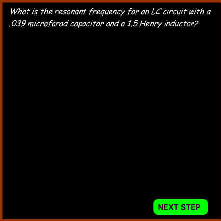
Example 1
 |
Identify resonance curves for series and parallel tuned circuits.
A series tuned circuit has a resonance curve which shows low attenuation at the frequency centre.
A parallel tuned circuit has a resonance curve which shows high attenuation at the frequency centre.
The values are still calculated using the formula above.
To produce a low impedance at the frequency centre the inductor and
capacitor are connected in series.To produce a high impedance at the
frequency centre the inductor and capacitor are connected in parallel
|
|
Understand the concept of the magnification factor Q as applied to the voltages and currents in a resonant circuit.
In a resonant circuit the term Q refers to the QUALITY of the output.
At resonance the voltage across the capacitor or inductor can be
several times that of the supply voltage. The Q of the circuit is equal
to the voltage across the reactance of the circuit divided by the
voltage across the resistance of the circuit. This is called the
magnification factor or Q.
A high Q circuit has a high voltage and a narrow bandwidth. So, in a
radio a high Q circuit will be harder to tune but be more selective.
A low Q circuit has a low voltage and a wide bandwidth. In a radio a low Q circuit will be easier to tune but be less selective.
When designing radios, different circuits require different Q values.
In an ATU a low Q is required in order to make tuning more easy. One setting will cover a wider frequency range.
In a VFO a high Q is required in order to produce a higher voltage to
drive the next stage and to produce a narrow frequency range.
Understand and apply the formula for Q factor given circuit component values.
The component Q is a measure of the Q of the circuit components. These are very important in determining the circuit Q. Using low Q components will result in a low circuit Q.
These are the two important equations:

In Example 2 if the resistance is
reduced to 2 ohm, the Q increases 5 fold to 15.7.
Usually capacitors have a high Q so when building a resonant circuit work on improving the Q of the inductor
Recall the definitions of the half power point and the shape factor of resonance curves.
The half power point is the energy in the resonant circuit "half" way between maximum energy and minimum.
In terms of dBs half means -3dBs. Remember that if we reduce the power
of a transmitter by 3dbs we halve it. The half power point can be
calculated from the maximum energy passing through a circuit x 0.707
Ideally the shape of a
filter should be rectangular with vertical sides. In the real world
filters have sloping sides or skirts. The shape factor is
a measure of the steepness of the skirts. The smaller the number,
the steeper are the response skirts.
Apply the equation for Q given the resonant frequency and the half power points on the resonance curve.
The circuit Q is calculated from the centre frequency and half power bandwidth

Where fC = centre frequency
fU = upper frequency at the half power point
fL = lower frequency at the half power point
Another method of calculating Q is to use the following formula:

Where Pi=3.14
f = frequency in Hz
C = capacitance in Farads
RD = the dynamic resistance of the circuit in ohms
In a parallel circuit
consisting of a coil, capacitor and resistor at resonance the
inductive reactance and capacitive reactance are equal and opposite, so
they cancel each other out. The resistance remaining is called the
dynamic resistance.
Note that Q does not have any units.
|
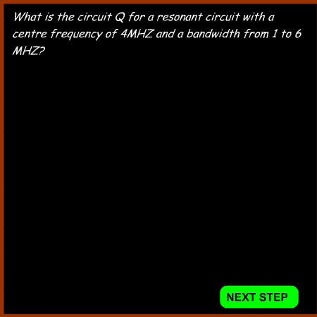
Example 2

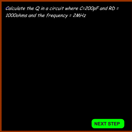
Example 3

Example 4

|

