| ADVANCED LESSON 46 |  |
| LEARNING OBJECTIVES and NOTES | |
| Automatic Gain Control | |
|
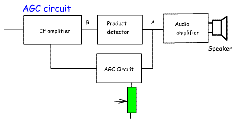
4p.1 Understand the derivation and use of an AGC voltage. As the signal increases in strength, the AGC reduces the level of amplification so that the audio stays at a fairly constant level and so that the IF amplifier is not overdriven causing distortion. The first stage is to sample the signal, This can be done at audio frequencies before the audio amplifier (point A) or at RF frequencies after the final IF stage (point R). The signal is rectified to produce a DC voltage which is used to control the IF gain of the receiver. There are chips specially designed to carry out all the functions of the AGC system. Some IF amplifiers require an increasing negative voltage to reduce their gain. In this case the positive voltage would have to be inverted to form a negative voltage. The AGC circuit may have switched capacitors to alter the delay time of the AGC and a variable resistor to adjust the threshold where the AGC starts to operate. |
 |
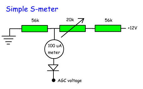
Recall that automatic gain control circuits can also be used to drive S meters. Most receivers have an S-meter to indicate the strength of the signal. This can be derived from the AGC circuit. In the simple circuit shown opposite a 50uV signal is applied to the 50 ohm antenna socket and the variable resistor adjusted for half scale deflection. This is S9. If an attenuator is available, introduce 6 dB attenuation. This is S8. Continue this until the meter is calibrated from S1 to S9. A 100uV input = S9+6dB A 500uV input = S9=20dB A more complex S-meter would include a transistor buffer to isolate the the AGC from the S-meter circuit. It should be noted that even commercial S-meters vary widely in their calibration. This is not too important as S-meters are generally used to give comparisons and of course in contests everyone is S9!!! |
 |