
| ADVANCED LESSON 48 | |
| LEARNING OBJECTIVES and NOTES | |||||||||||||||||||||||||||
| Antenna feeder basics | |||||||||||||||||||||||||||
|
5a.1 Understand that the velocity factor of a feeder is the ratio of
the velocity of radio waves in the feeder to that in free space and
that the velocity factor is always less than unity. Calculate physical feeder lengths given the frequency and velocity factor. Recall that the velocity factor for coaxial feeder with a polythene dielectric is approximately 0·67 or 2/3. Recall that feeder loss increases with increasing frequency and that lower loss feeders may be desirable at VHF, UHF and above. It is a fact that radio waves do not travel as fast along a feeder as they do in free-space. The term used to describe this ratio is the velocity factor which equals: The velocity travelled in the feeder / The velocity of light or radio waves in free space. The velocity of light  The velocity factor will always be less than 1. The feeder loss increases as the frequency rises The table opposite shows the loss in power (given in dBs) as frequency increase for 3 types of coax. For example using RG58 coax the loss in 100m is 20dB at 2m and 40dB at 70cm. So, is we use 100m of RG58 to feed a 2 m antenna there is a loss of 20dB = 3.3 S points! If we use 100m of LDF coax the loss drops to 2.5dB (less than half an S point. If we use the same feeders at 70cm the loss with RG58 is 40dB (6.6 S Points) If we use the LDF450 the loss is 4.0dB at 70cm. |
Example 1
|
||||||||||||||||||||||||||
5a.2 Understand that a quarter-wave length of feeder can be used as an impedance transformer. Apply simple examples of the formula Z02=Zin×Zout. A quarter wave length of coax can be used to match two different impedances. For example a 3 element beam may have an impedance at the feed point of 25 ohms. If we want to match this to 50 ohm coax this could be achieved by connecting a quarter wave of 35 ohm coax between the antenna feed point and the 50 ohm coax. A 2 element quad having a feed point of 100 ohms could be matched to 50 ohm coax using a quarter wave of 75 ohm coax. The general formula is  Where: Z02 = impedance of coaxial cable Zin = input impedance of antenna Zout = output impedance of rig (usually 50 ohm) |
 Example 2 
Example 3
 |
||||||||||||||||||||||||||
|
5a.3 Recall the basic construction and use of waveguides. Wave guides are used at microwave frequencies. They consist of metal tubes which can be circular or rectangular. There is no centre conductor. Signals pass along the guide by total internal reflection from the walls. The dimensions of the tube dictate the upper and lower frequencies that can be "guided " along the tube. Given the high losses of coax at these frequencies waveguides show much less loss although they are more expensive to make / buy. |
 |
||||||||||||||||||||||||||
| Baluns | |||||||||||||||||||||||||||
|
5b.1 Recall the construction and use of transformer, sleeve and choke type baluns. A balun is used to transfer RF power from a balanced system to an unbalanced system. baluns can also be used to convert from one impedance to another. If we first look at some situations where a balun is used to connect a balanced to an unbalanced system.
Baluns consist of 2 or more wires wound round a ferrite ring or rod. A 4:1 balun has a about 17 turns consisting of two parallel wires wound round the ferrite. A 1:1 balun has about 17 turns consisting of three parallel wires wound round the ferrite. The drawings show how baluns are connected up. There are other ways of constructing baluns: A choke balun consists of a coil of coax either with or without a ferrite ring. These are often used just below an antenna to stop RF current flowing down the braid of coax. Choke balun 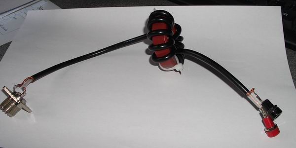 A sleeve balun consists of a length of coax with ferrite rings threaded on the outside. 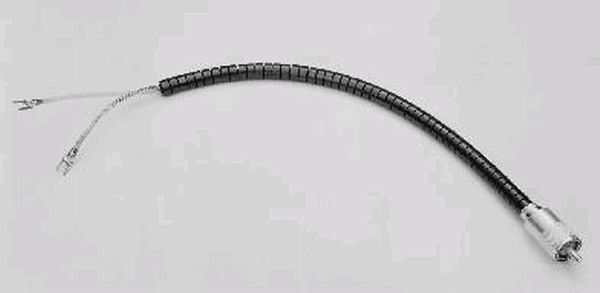 |
|