| ADVANCED LESSON 49 |  |
| LEARNING OBJECTIVES and NOTES | |||||||||||||||||
| Antennas 1 | |||||||||||||||||
|
5c.1 Recall the equation for calculating half-wavelengths and be able
to apply ‘end factor correction’ in calculating the approximate physical
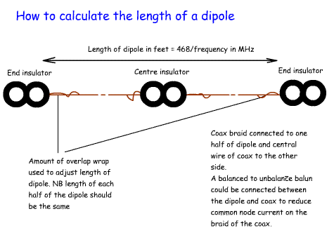
lengths of dipole elements. The length of a half wave dipole in feet is calculated from the equation: Length of dipole = 468 / freq in MHz Example What is the length of a half-wave dipole for 7.100MHz Length of dipole = 468/7.100 = 65.9 feet In practice cut the wire to a little longer than calculated. Cut this in half and connect the coax feeder. The braid goes to one side and the inner of the coax to the other side. An insulator will be required in the centre of the dipole to support each wire. If the wire is uninsulated connect an insulator at each end by wind ing some of the wire back on itself. Do the same at each end. Put the antenna into position and check the SWR. If it is too high reduce the length by wrapping more wire back on itself at each end. Reduce the length on each side by exactly the same amount. If the SWR is getting higher you need to shorten it a bit. Eventually you should get an SWR better than 1.5 to 1. This formula takes into account the "‘end factor correction’ which means a reduction in length of about 5% at each end brought about by the attachment of an insulator at each end which introduces capacitance. In addition if the antenna is made from insulated wire it will be shorter than if using bare wire. Also, the diameter of the wire related to the frequency will also have an effect. The figure of 468 comes about from a series of experiments carried out in 1926 where the length of dipoles at different heights was measured. 468 was the average value and could be too short at certain heights. So, 468 is a guide but to be sure cut your dipole a bit longer! The formula: 
 Where V = C = velocity of light = 3 x 10⁸ m/s f = frequency in Hz lambda = wavelength in metres 1 metre = 3.281ft |
 |
||||||||||||||||
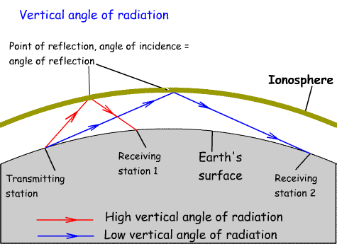
5c.2 Recall that the angle at which the propagated radio wave leaves the antenna is known as the (vertical) angle of radiation and that longer distances require a lower angle of radiation. Recall the effect of the ground on the angle of radiation. For long distance communication via the ionosphere we want an antenna that has a low vertical angle of radiation. For short range communication via the ionosphere we want a high vertical angle of radiation. In general low dipoles put most of their energy at a high angle. Vertical antennas have much lower angles of take off. In addition a good reflective surface will help to lower the angle of radiation from a vertical antenna. A good reflective surface could include salt water, the metal hull of a ship, many radials, or at VHF a car roof. Operating a dipole from sloping ground can also help to improve low angle take off. |
 |
||||||||||||||||
|
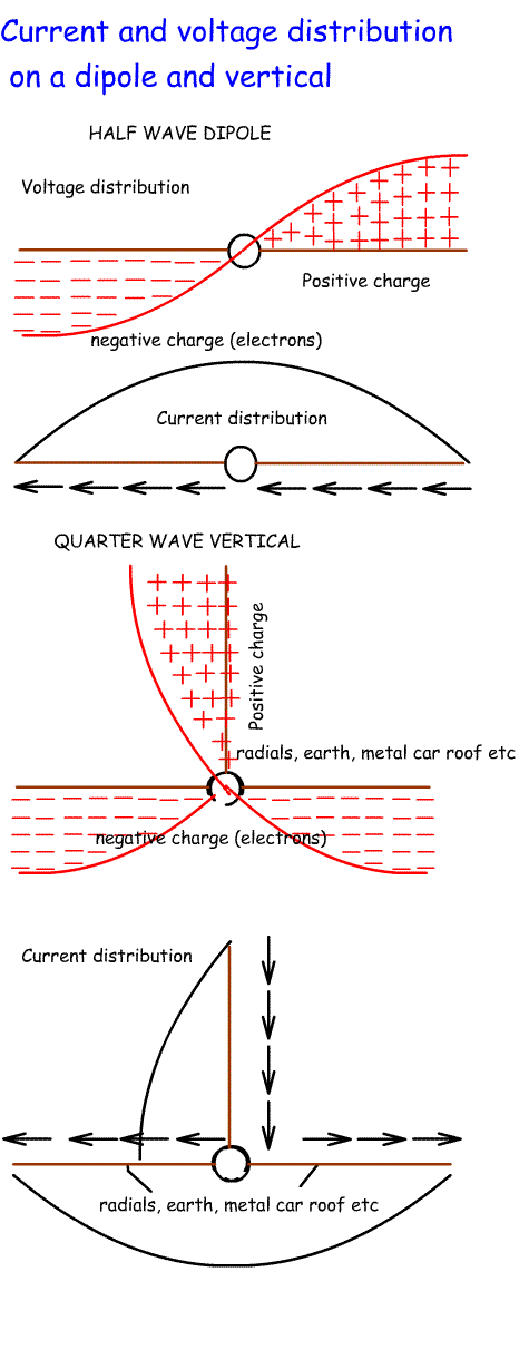
5c.3 Recall the current and voltage distribution on the dipole and λ/4 ground plane antennas. Recall the feed-point impedances of half-wave dipoles, quarter-wave and loaded 5λ/8 verticals, folded dipoles, full-wave loops and end fed λ/4 and λ/2 antennas. Recall the effect of passive antenna elements on feed point impedance and the use of folded dipoles in Yagi antennas. A dipole has a high current in the centre and a low current at the ends. A dipole has a low voltage in the centre and a high voltage at each end. A quarter wave ground plane has a high current at the base and a low current at the end. A quarter wave ground plane has a low voltage at the base and a high voltage at the end. As the centre of a dipole is fed by an alternating RF energy, the positive and negative sides will be constantly changing positions. A vertical works the same way, but this time the wire is vertical and the "other side" of the antenna is made up of horizontal wires or something similar. The current and voltages in the horizontal parts will cancel each other out (assuming there are least 2 of them) leaving the vertical section to radiate. If the earth is used as "other side" of the vertical radiation will depend on the efficiency of the earth at carrying current. Salt water is very conductive and forms a good reflector. Dry sand is a poor conductor and forms a poor reflector. The feed impedance varies with the type of antenna and its location. These are approximate figures:
|
 |
||||||||||||||||
| The effect of passive elements (or parasitic elements) on the feed impedance of a Yagi and other beam antennas. A beam antenna consists of a driven element connected to the TX / RX, a reflector and a number of directors. If we used a dipole as the driven element every time we add a closely spaced director or reflector element the impedance of the dipole will fall. To overcome this problem a folded dipole is often used as the driven element. This starts off with an impedance of 300 ohms. If we add sufficient directors the impedance of the folded dipole will fall to 50 ohms and we can connect the output from our TX/RX directly to the folded dipole. Another method of matching beams to feeders is to use a gamma-match. |
|
||||||||||||||||
| Antenna Gain Antenna gain is measured in dBs. The base line for this figure is often given as an isotropic antenna. This is an imaginary antenna consisting of a single point in space which radiates an equal signal in all directions. Given that all real antennas put more power in one direction than another, all antennas will have some gain over an isotropic antenna at a particular frequency. A dipole is often quoted as having a 2.15dB gain over an isotropic antenna. This means that if a Yagi is quoted as having a 10dB gain over an isotropic antenna it will have a 7.85(10-2.15) dB gain over a dipole. The gain of a Yagi antenna is calculated from the formula:  The effective radiated power from an antenna can be calculated from the formula:  |
|