
QRP Topband Transmitter.
The design that follows is for a QRP 160m band AM transmitter that will transmit an undistorted NBTV waveform and is based on an original design by the BRATS (a Kent radio club). Crystal control was chosen for simplicity and as single channel use was only considered necessary.

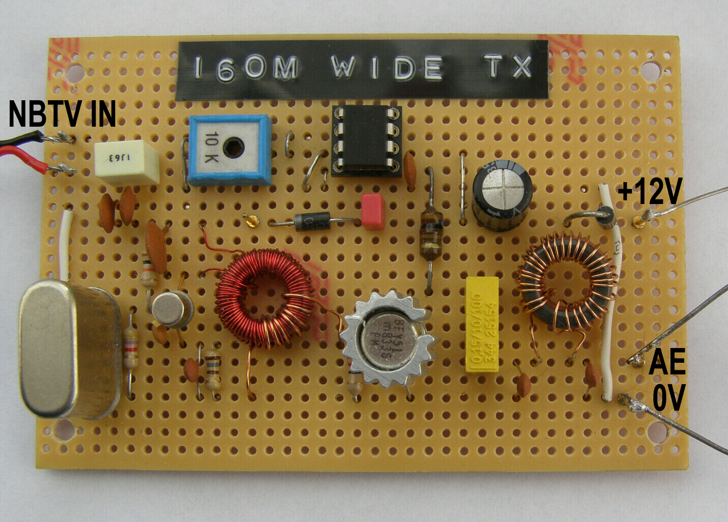
The Circuit for NBTV 'Audio' Line In (Drawn by G6PKS) A Working Layout (Built by G4AYT)
Notes
This transmitter will output in excess of 500mW with a 13.8V supply, but the output transistor and modulating IC will get very hot, so suggest restricting to around the 350mW mark. Another diode in series with the supply will usually do the trick, although dropping the supply voltage too much will distort the transmitted waveform. An easy method to measure and calculate this low power level is shown below. A heatsink should be fitted to the BFY51 output transistor.
The output is designed to match a 50R load with 1 : 1 SWR, so an external ATU may be necessary. The antenna at G4AYT is a 20m base loaded vertical tuned against a good ground system, giving a perfect match.
We chose to standardise on 1.940kHz as a supply of crystals for that frequency was available on Ebay at the time. The original design was for slightly higher in frequency, so we added an extra turn to the oscillator collector load (71 turns instead of the 70 turns shown).
Versatility could be increased by adding a switch at the audio input to switch in a mic pre-amp so the TX can also be used for phone operation as well as NBTV.
Obviously further amplification can be used with a linear amplifier should more power be required.
To measure then calculate low powers the method below is quite accurate for all HF/LF amateur bands.
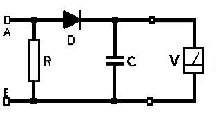
Set up the circuit opposite across the aerial/earth terminals of the transmitter. R is a load resistor (NOT wirewound) and should be 50 Ohms or close to and rated at a watt or so. D is either a silicon or germanium diode. C is a 1nF (1000pF). V is the station multimeter set to the 10V range. Layout is in no way critical.
Apply power to the transmitter without modulation and note the reading on the voltmeter. An oscilloscope may be connected in place of the voltmeter, or later to check modulation levels if required.

Turning to the formula, power P can be calculated in watts, using your voltage reading, but remember there is a voltage drop across the diode, so before putting V into the formula, add 0.25 if using a germanium diode (e.g. OA47) or 0.7 for a silicon diode (e.g IN4148). R is the value in Ohms of the load resistor used.
Practical result example with the TX board shown above: R was 47 Ohms (2W), D was a IN4148. Measured voltage was 6.5V with a supply voltage of 13V, so V for the formula is 7.2V. Calulating 7.2 squared then divided by 94 gives a power of 551mW, a tad too much, so the supply voltage needs dropping further. At this power level the 47 Ohm resistor, even though rated at 2W, gets quite warm.
The Receiver
Research and development on going, progress will be reported here shortly.
A homebrew wideband TRF type RX has been tried and works well with a very strong signal, but further bandwidth adjustments are needed to reduce noise and unwanted signals.