IN3OTD's web site
...under perpetual construction.

Some measurements on common-mode chokes for antennas
Recently I installed a good old 14AVQ vertical antenna and while checking the signal on the various bands I noticed a few frequencies with a quite high broadband noise, which at the beginning I thought coming from some devices in the neighborhood. But some quick checks pointed actually to some sources inside the house; it took little time to realize that all was due to the homebuilt PC power supply.
This surprised me a bit, as I bought that particular PSU also because it was advertising a "Double Layer EMI Filter" - and showing a picture of two filter sections on the mains input on the product web page - which I thought should be much better than the common "no-name" ATX PSU.
Checking the RF emissions with a small loop connected to the HF receiver, I saw that the noise was radiated from all the wires connected to the PC, but was stronger near the mains cable.
A first try winding a few turns of the supply cable around a FT240-31 (Fair-Rite 2631803802) did reduce the noise but just a little. Then I noticed that also the coaxial cable in the shack, connected to the vertical antenna, appeared to radiate the noise. I was a bit puzzled but then I thought that likely the cable was just the right length to appear as a low-impedance connection the the external ground: winding a few turns of the coaxial cable on the above-mentioned toroid reduced the noise below the received noise floor.
Chokes impedance and equivalent circuit
The nice table from G3TXQ shows in a compact, easy to read, table a few suggested configurations for a common-mode choke but I was curious to check if I could replicate the same results here.
I have then measured several chokes wound by connecting them directly in series between the two ports of a VNA, similarly to what has been done by G3TXQ but without the additional loading resistor on the first port, as is not really needed for a proper measurement.
From the measured S-parameters the component values of an equivalent circuit model (shown below) were calculated
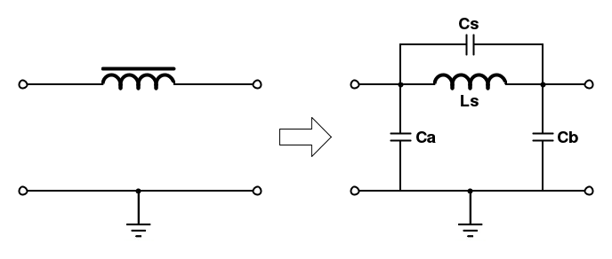
Besides the usual parallel resonant circuit in series between the two ports, the model also includes the parasitic capacitance to ground at every port. These two capacitance are often not considered but is interesting to have an idea of their values and possible loading effects on the circuit.
All the tested chokes were wound with the same length of (cheap) RG-58 cable (about 3 meters) on the same FT240-31 (Fair-Rite 2631803802) toroid.
The bending radius of the coaxial cable was kept at about 1 inch, the minimum usually recommended for this type of cable.
The VNA ports were connected to the shield of the cable, using crocodile clips; the effect of the connecting cables was removed by the VNA calibration and the parasitic capacitance of the crocodile clips alone was subtracted from the measurements.
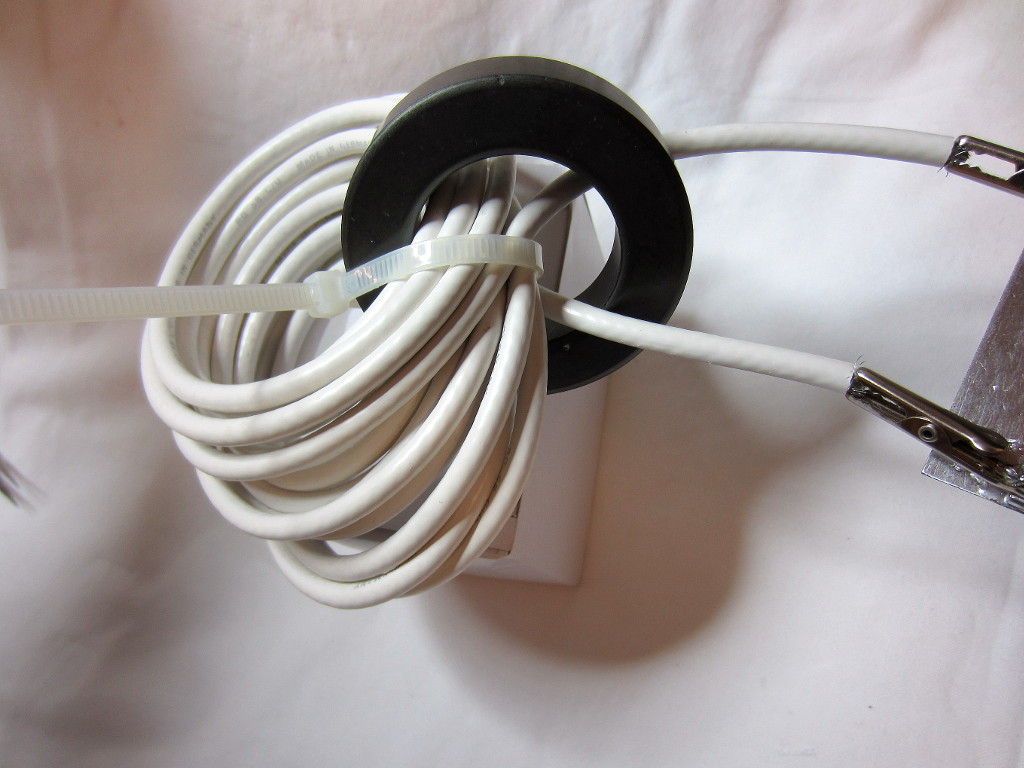
Random-wound choke, 14 turns
The first choke measured was wound without paying particular attention to the turns spacing and size,
Here are the equivalent circuit parameters computed from the measured S-parameters.
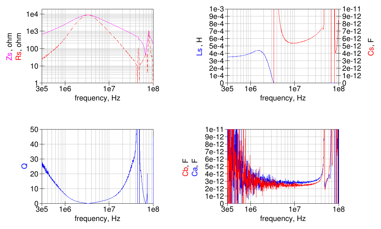
The choke has a parallel resonance at about 3 MHz where its impedance peaks at around 9 kΩ. The equivalent parallel capacitance is about 5.5 pF; the capacitance to ground of each side is about 2.5 pF.
Note that at higher frequencies there are other parallel and series resonances, all above the HF band.
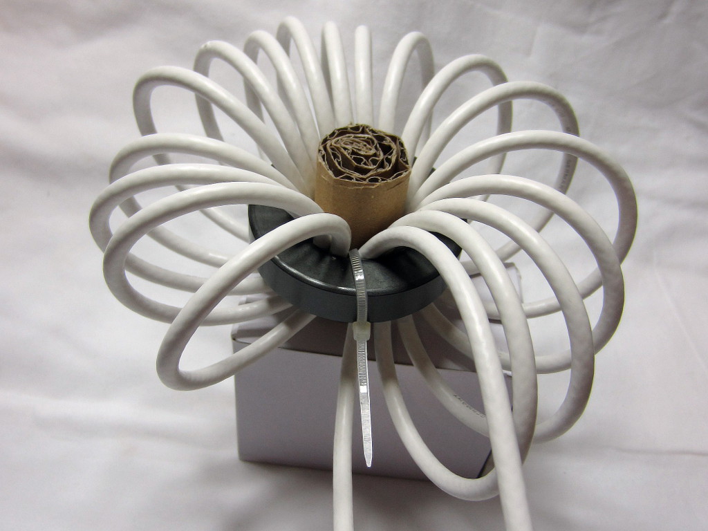
Standard-wound choke, 18 turns
This choke was more properly wound, without overlapping turns and distributing them equally around the toroid. A piece of rolled corrugated cardboard was inserted in the middle to keep the turns from moving and overlapping.
As shown below, there is a better way to keep the turns neatly in place.
Here are the equivalent circuit parameters computed from the measured S-parameters.
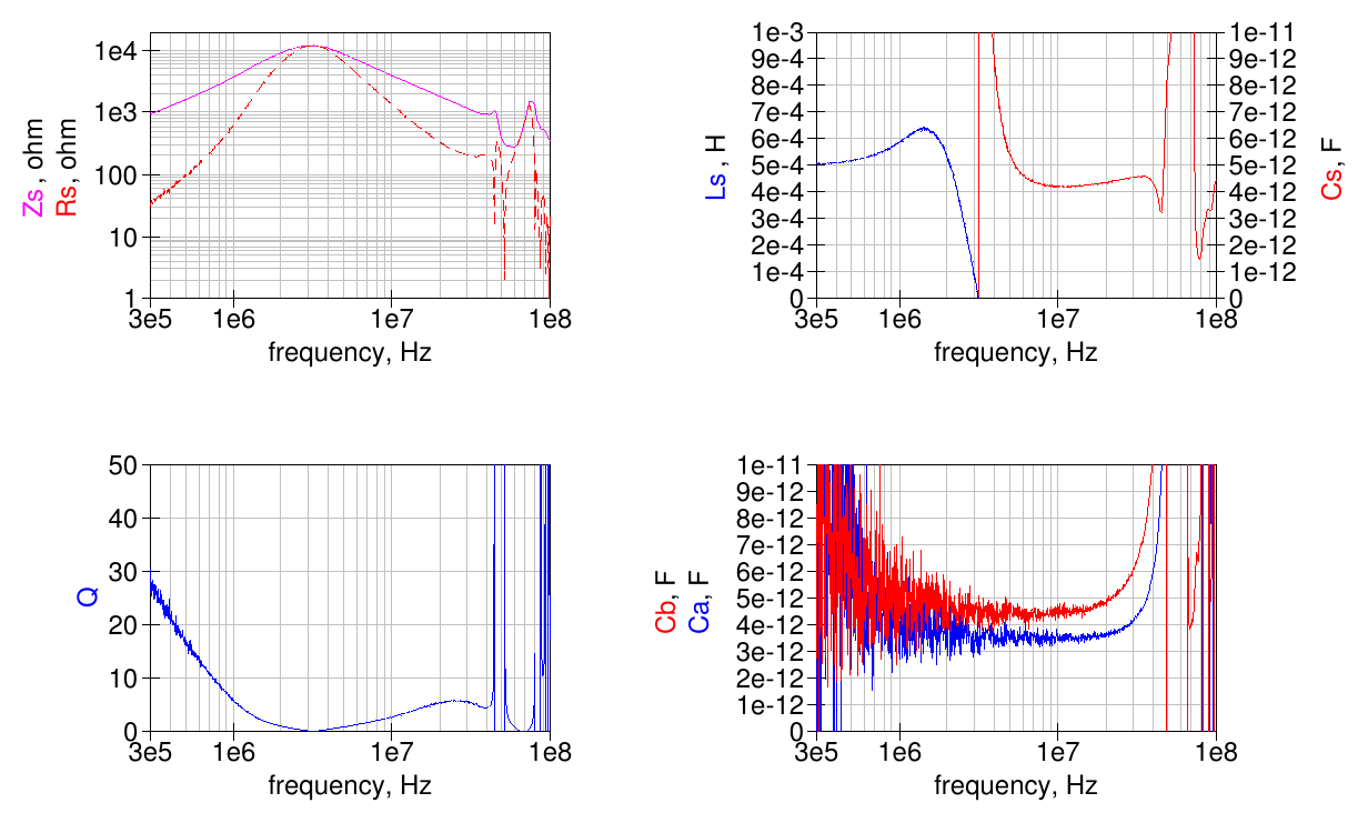
The choke has a parallel resonance at about 3 MHz, like the previous one, but reaches an impedance peaks of slightly over 10 kΩ. The equivalent parallel capacitance is about 4 pF; the capacitance to ground of each side is about 4 pF.
This choke is better than the previous one in several ways: it has a higher low-frequency impedance, a higher peak impedance and a lower parallel capacitance, which means that also its high-frequency impedance, above the parallel resonance, is also higher.
Split-winding choke, 18 turns
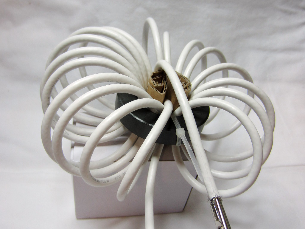
Similar to the previous choke, wound with the same number of turns but with the so called split-winding (or cross-over) technique; half of the turns are wound on the toroid, then the wire is passed thru the toroid and the winding is continued starting near the first turn and going toward the half just wound. Easier to do than to describe, hi.
The usual piece of rolled corrugated cardboard is used to keep the turns in place.
Here are the equivalent circuit parameters computed from the measured S-parameters.
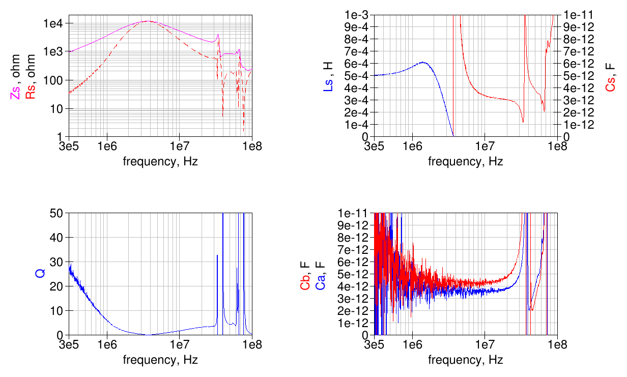
The choke parallel resonance is shifted up to almost 4 MHz, peak impedance is still slightly over 10 kΩ. The equivalent parallel capacitance is about 3 pF; the capacitance to ground of each side is about 4 pF.
The split-winding as brought a significant reduction in the parasitic capacitance, so the parallel resonance is shifted up and the high-frequency impedance, above the parallel resonance, is also higher than the standard-wound choke.
Note that this winding style has changed the high-frequency series and parallel resonances position; there is now another, narrow, parallel resonance just above the HF band.
There are different views on the general usefulness of using the split-winding technique for chokes but it seems to me that the reduction in the parasitic parallel capacitance can only be beneficial.
A spacer for easier winding
One of the problem in winding a relatively large number of loose turns around a toroid is keeping them properly in place, to avoid overlapping them and/or having the choke partially unwind by itself.
An easy solution is to use a spacer with appropriate holes for the turns, firmly inserted inside the toroid. The friction on the wire will keep the choke from unwinding and the holes position will ensure a consistent spacing for the turns
A spacer like this will probably be an easy job for those having a 3D printer; in a hurry I quickly made one from a piece of wood, as shown below:
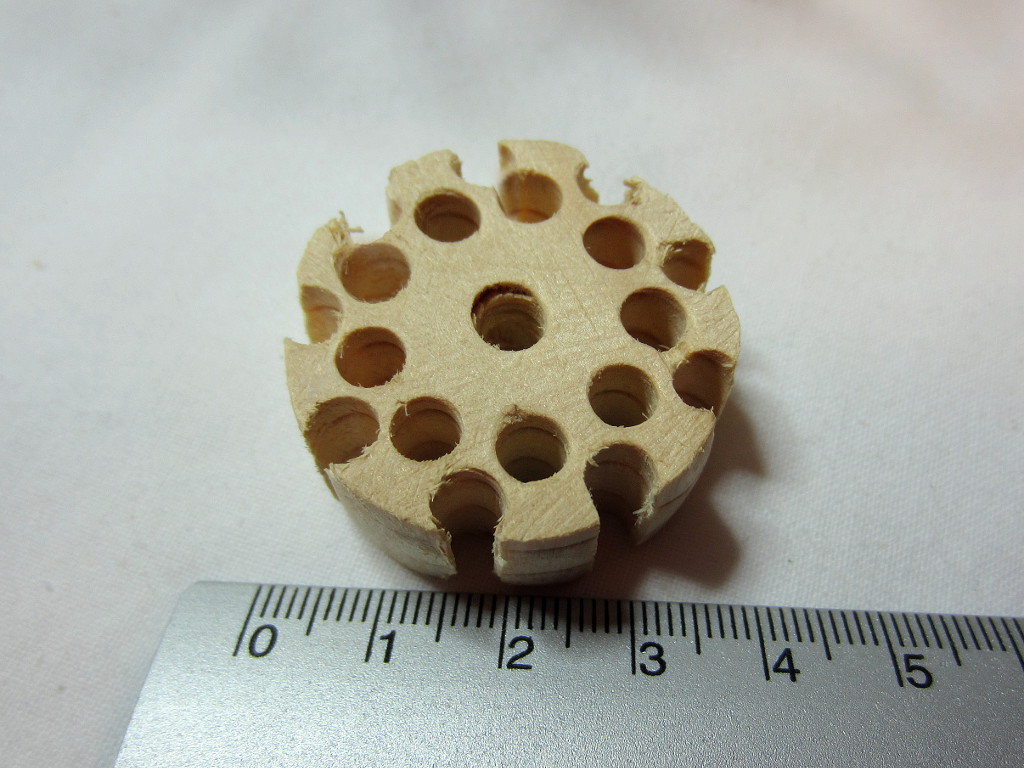
It doesn't look very nice but, well, it does the job. It was made with the objective of winding the usual 18 turns and trying to further reduce the parasitic capacitance between the turns. There are 9 holes equally spaced around the circumference and other 9 on a circle with a smaller diameter; the idea is to keep some spacing between adjacent turns where they pass closest to each other to reduce the capacitance. Another hole in the middle can be used for a cross-over winding style.
Here below are a couple of common-mode chokes built using this spacer.
Standard-wound choke with spacer, 18 turns
The usual choke with 18 turns, kept in place using the spacer described above:
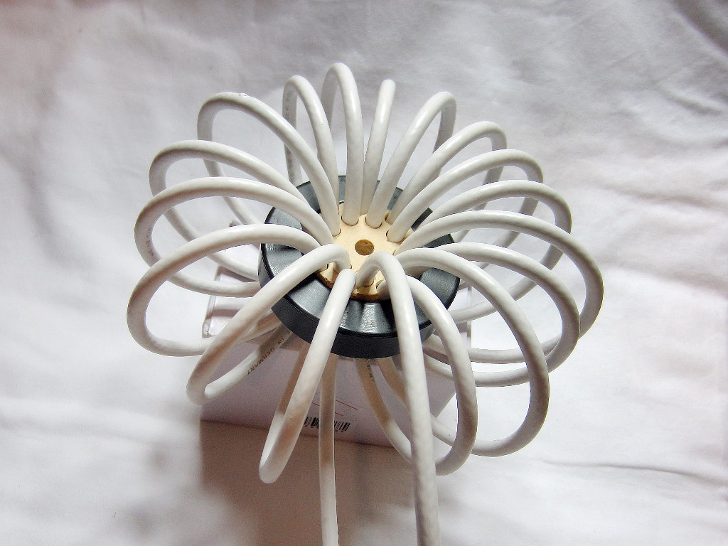
Here are the equivalent circuit parameters computed from the measured S-parameters.
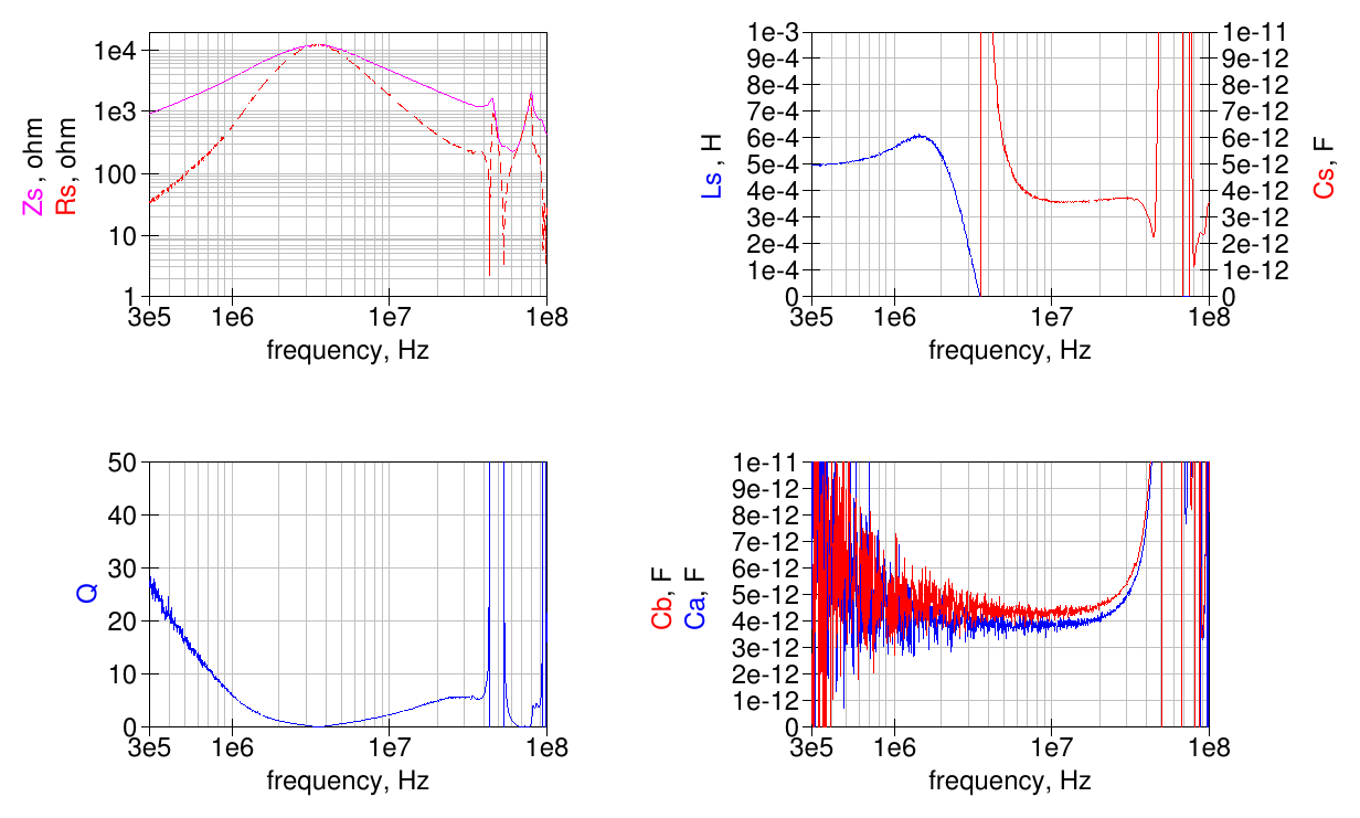
The parallel resonance is around 3.5 MHz, the peak impedance peaks is slightly over 10 kΩ. The equivalent parallel capacitance is about 3.5 pF, slightly lower than the equivalent choke built without the spacer. It seems the added space between turns in the inside of the toroid helps somewhat.
Split-winding choke with spacer, 18 turns
Last variation is using the split-winding technique with the spacer:
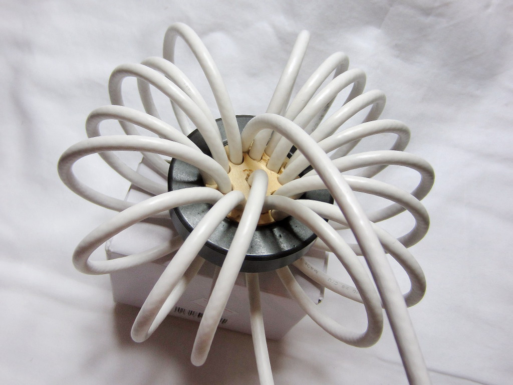
Here are the equivalent circuit parameters computed from the measured S-parameters.
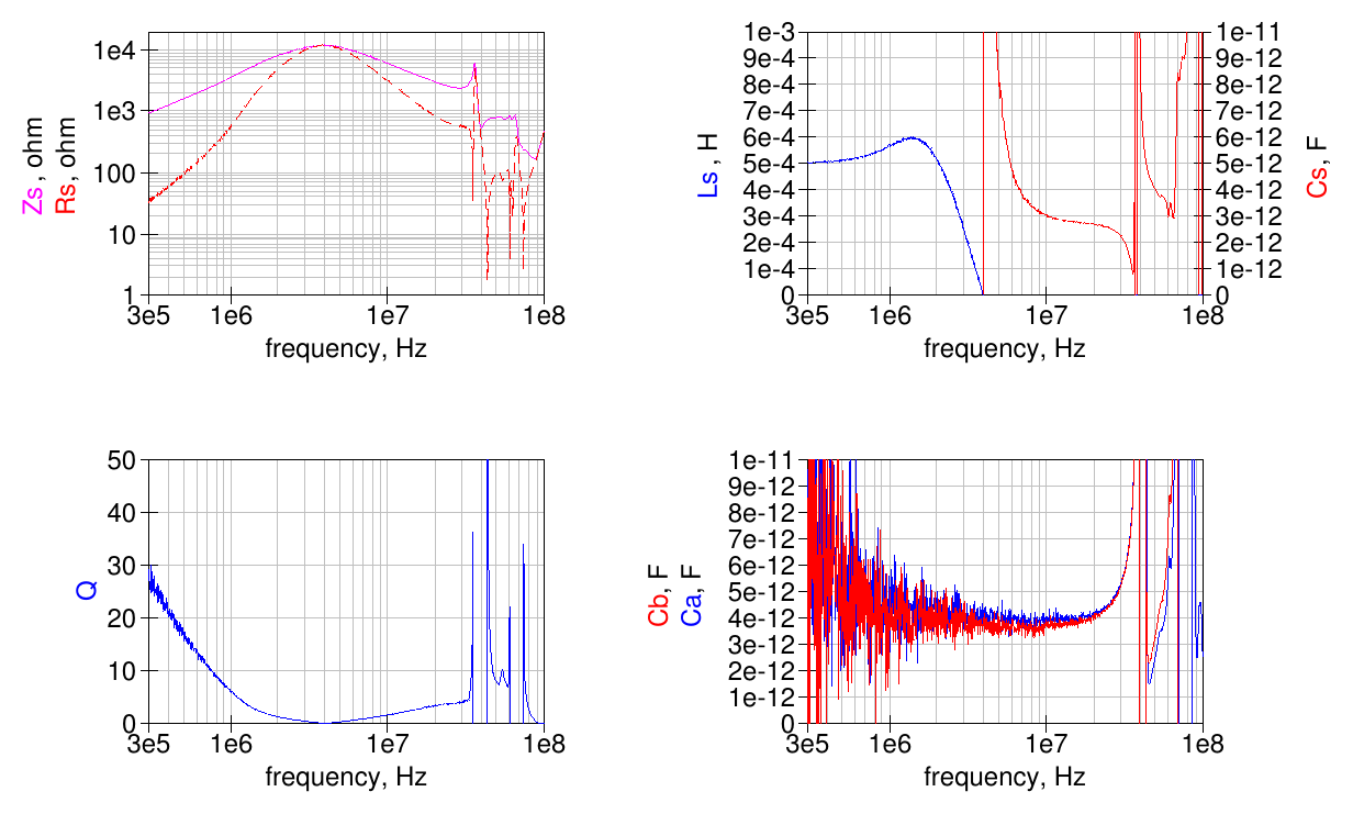
Now the parallel resonance is shifted up to 4 MHz; peak impedance is still slightly over 10 kΩ. The equivalent parallel capacitance is below 3 pF.
This is a further improvement over the split-winding choke without spacer.
As seen before, this winding style has changed the high-frequency series and parallel resonances position.
Measurements summary
Graph with the series impedance and its resistive part for all the chokes described above:
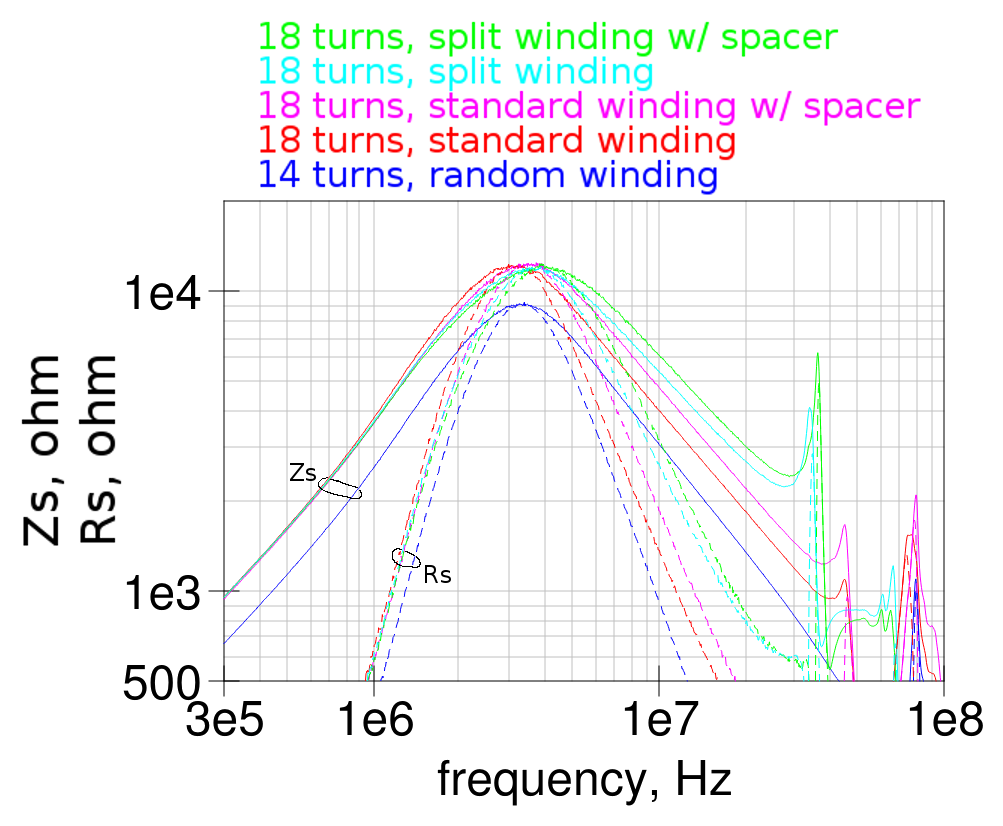
Note that the random-wound choke has the higher parasitic capacitance, even if wound with less turns, while the split-wound choke with the turns spacer has clearly the best performances.
The split winding brings some parasitic resonances near the higher end of the HF spectrum but in this particular case these are still sufficiently above 30 MHz.