Enclosure Construction
|
|
|
|
|
|
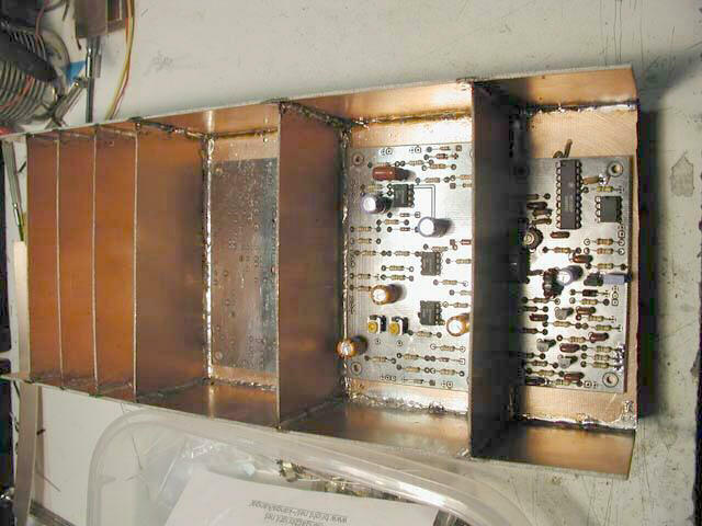
This is the same side as in the previous photo, just making sure the boards fit OK. Shortly after this photo, I drilled the holes for the screws to go through the board and into the stand offs that hold the board up. First I had drilled the holes for the 10MHz Resolution Filer, then the LogAmp. After drilling the Log Amp holes, I realized that two of the holes were too close to the holes for the filter board and that I had to redo them. Fortunately, I had lots of room on the Log Amp side, due to the extra vertical space needed by it's next door neighbor, the Timing Base.
After redrilling the holes for the Log Amp board, I repaired the now extra holes using small strips of solder wick. As you might guess, I used a fair amount of solder wick on this project, and I always save the wicked up pieces. They are perfect for fixing small holes in PCB material (such as needed here just to make sure the sections were RF-tight), for making ground straps, etc.