Chameleon CHA F-Loop Antenna Parameters: 5-30 MHz
|
||||||||||||||||||||||||||||||||||||||||||||||||||||||||||||||||||||||||||||||||||||||||||||||||||||||||||||||||||||||
|
1. This curve of the measured SWR demonstrates the 18
kHz 2:1 VSWR bandwidth of the CHA F-Loop antenna when
the capacitor is adjusted for 5.3 MHz. The SWR minimum
at 5.295 MHz is 1.168:1. |
||||||||||||||||||||||||||||||||||||||||||||||||||||||||||||||||||||||||||||||||||||||||||||||||||||||||||||||||||||||
|---|---|---|---|---|---|---|---|---|---|---|---|---|---|---|---|---|---|---|---|---|---|---|---|---|---|---|---|---|---|---|---|---|---|---|---|---|---|---|---|---|---|---|---|---|---|---|---|---|---|---|---|---|---|---|---|---|---|---|---|---|---|---|---|---|---|---|---|---|---|---|---|---|---|---|---|---|---|---|---|---|---|---|---|---|---|---|---|---|---|---|---|---|---|---|---|---|---|---|---|---|---|---|---|---|---|---|---|---|---|---|---|---|---|---|---|---|---|---|
|
2. This curve of the measured SWR demonstrates the 24
kHz 2:1 VSWR bandwidth of the CHA F-Loop antenna when
the capacitor is adjusted for 7.1 MHz. The SWR minimum
at 7.1 MHz is 1.345:1. |
||||||||||||||||||||||||||||||||||||||||||||||||||||||||||||||||||||||||||||||||||||||||||||||||||||||||||||||||||||||
|
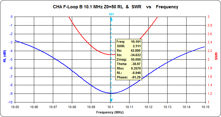
3. At 10.1 MHz the SWR minimum is 2.111:1. |
||||||||||||||||||||||||||||||||||||||||||||||||||||||||||||||||||||||||||||||||||||||||||||||||||||||||||||||||||||||
|
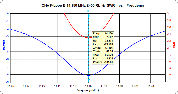
4. At 14.15 MHz the SWR minimum is 2.292:1. |
||||||||||||||||||||||||||||||||||||||||||||||||||||||||||||||||||||||||||||||||||||||||||||||||||||||||||||||||||||||
|
5. At 18.1 MHz the SWR minimum is 2.232:1. |
||||||||||||||||||||||||||||||||||||||||||||||||||||||||||||||||||||||||||||||||||||||||||||||||||||||||||||||||||||||
|
6. This curve of the measured SWR demonstrates the 30 kHz 2:1 VSWR bandwidth of the CHA F-Loop antenna when the capacitor is adjusted for 21.2 MHz. The SWR minimum at 21.2 MHz is 1.953:1. |
||||||||||||||||||||||||||||||||||||||||||||||||||||||||||||||||||||||||||||||||||||||||||||||||||||||||||||||||||||||
|
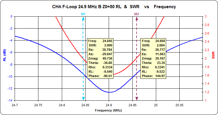
7. This curve of the measured SWR demonstrates the 113 kHz 2:1 VSWR bandwidth of the CHA F-Loop antenna when the capacitor is adjusted for 24.9 MHz. The SWR minimum at 24.9 MHz is 1.607:1. |
||||||||||||||||||||||||||||||||||||||||||||||||||||||||||||||||||||||||||||||||||||||||||||||||||||||||||||||||||||||
|
8. This curve of the measured SWR demonstrates the 181 kHz 2:1 VSWR bandwidth of the CHA F-Loop antenna when the capacitor is adjusted for 28.4 MHz. The SWR minimum at 28.4 MHz is 1.294:1. |
||||||||||||||||||||||||||||||||||||||||||||||||||||||||||||||||||||||||||||||||||||||||||||||||||||||||||||||||||||||
|
9. Plot of measured Magnetic Loop Antenna Impedance at
Zero Reactance vs. Frequency. |
||||||||||||||||||||||||||||||||||||||||||||||||||||||||||||||||||||||||||||||||||||||||||||||||||||||||||||||||||||||
|
10. Plot of measured 2:1 VSWR bandwidth at Zero Reactance
vs. frequency. |
||||||||||||||||||||||||||||||||||||||||||||||||||||||||||||||||||||||||||||||||||||||||||||||||||||||||||||||||||||||
|
11. Plot of calculated Magnetic Loop Antenna Q vs. Frequency. (Calculator on http://owenduffy.net/calc/VswrBw2AntQ.htm) |
||||||||||||||||||||||||||||||||||||||||||||||||||||||||||||||||||||||||||||||||||||||||||||||||||||||||||||||||||||||
|
12. Plot of calculated Magnetic Loop Antenna Free Space Efficiency vs. Frequency. (Calculator at http://owenduffy.net/calc/SmallTransmittingLoopBw2Gain.htm)
|
||||||||||||||||||||||||||||||||||||||||||||||||||||||||||||||||||||||||||||||||||||||||||||||||||||||||||||||||||||||
|
13. Plot of calculated Magnetic Loop Antenna Free Space Gain vs. Frequency. (Calculator at http://owenduffy.net/calc/SmallTransmittingLoopBw2Gain.htm) |
||||||||||||||||||||||||||||||||||||||||||||||||||||||||||||||||||||||||||||||||||||||||||||||||||||||||||||||||||||||
|
14. Azimuth Radiation
Patterns for CHA F-Loop Antenna modeled for 14, 21 and
28 MHz at 5 feet above Average Ground (4nec2
model). These gains are greater than the free
space values due to the additive effect of ground
reflection. |
15. Elevation Radiation Patterns for CHA F-Loop Antenna modeled for 14, 21 and 28 MHz at 5 feet above Average Ground (4nec2 model). These gains are greater than the free space values due to the additive effect of ground reflection. |
|||||||||||||||||||||||||||||||||||||||||||||||||||||||||||||||||||||||||||||||||||||||||||||||||||||||||||||||||||||
|
|
||||||||||||||||||||||||||||||||||||||||||||||||||||||||||||||||||||||||||||||||||||||||||||||||||||||||||||||||||||||
DISCUSSIONThe observed parameters correlate with the NEC model predictions, except for an additional 2-3 dB loss on 5 and 7 MHz with the antenna in the "A" switch position likely due to increased ground losses at those frequencies and the insertion of capacitor rotor contact and switch contact resistance into the radiator loop circuit. (The revised design of this antenna substitutes a capacitor of greater range and allows continuous tuning from 7 through 30 MHz through the dual capacitor gangs in series). I had initially suspected that the ring terminal connections in the radiator loop circuit were responsible for the CHA F-Loop's lower Q than a similar comparison antenna4 with ceramic stator supports. However, these data reveal that the dual gang capacitor's phenolic stator supports are the more significant factor yielding a capacitor Q factor that decreases from 1500 at 10 MHz to near 100 at 28 MHz. Soldering the capacitor connections to the SO-239s and substituting a capacitor with ceramic stator supports could theoretically improve the gain at 28 MHz by 5 dB (nearly one S unit) but at a prohibitive increase in material cost and weight. With its existing capacitor, the resistive losses from the ring terminal connections to the SO-239s are relatively insignificant. The predicted CHA F-Loop azimuth radiation pattern in Figure 14 appears nearly omni-directional, becoming more directional with its feed point and the capacitor positions exchanged, placing the capacitor above and the feed point below as in the comparison antenna4. Such directivity may be desirable when local radio frequency noise needs to be minimized, but its implementation can affect other considerations such as physical stability and proximity effects during antenna tuning. The location of the heavier capacitor tuning box at the bottom does offer greater physical stability when resting on a flat surface and greater radiation efficiency when resting on the ground or another reflective surface, but it also brings the high voltage ends of the radiating loop into proximity to the user during adjustment and likewise causes a variable change in antenna frequency after removing the hand from the tuning knob. The fixed ratio style coupling loop typically exhibits some impedance mismatch over this wide frequency range. Indeed the CHA F-Loop non-reactive feed point impedance at resonance varied from 9.9 ohms at 5.3 MHz to 38.4 ohms at 28 MHz. The customary 5:1 loop diameter ratio would suggest a 5.9 inch coupling loop instead of the CHA F-Loop's 8 inch loop. A different coupling loop diameter may yield a lower minimum SWR with the overall non-reactive feed point impedance closer to 50 ohms. |
SPECIFICATIONS AT SWR MINIMA (Z0 = 50 Ω)
|
|||||||||||||||||||||||||||||||||||||||||||||||||||||||||||||||||||||||||||||||||||||||||||||||||||||||||||||||||||||
| Frequency MHz |
5.3 |
7.1 |
10.1 |
14.15 |
18.1 |
21.2 |
24.9 |
28.4 |
|---|---|---|---|---|---|---|---|---|
| Impedance ohms |
44+j5 |
57-j14 |
43-j35 |
32-j29 |
27-j21 |
28-j13 |
32-j7 |
39-j2 |
| SWR |
1.168 |
1.345 |
2.111 |
2.292 |
2.232 |
1.953 |
1.607 |
1.294 |
| 2:1 SWR bandwidth kHz |
18 |
24 |
N/A |
N/A |
N/A |
30 |
113 |
181 |
Polarization: Vertical at low elevation
angles transitioning to horizontal at high elevation
angles.
Power Rating: 10 watts CW or 25 watts SSB
per manufacturer.
Frequency range: Switch position A 5.3-24.4
MHz; Switch position B 7.5-31.3 MHz
ANTENNA PARAMETERS: Measured vs. NEC Model
Predicted Efficiency and Free Space Gain
| Frequency MHz |
Z0 ohms |
2:1 SWR BW kHz* |
Q** | Eff. %** | Model Eff. %*** |
Free Space Gain dBi** |
Model Gain dBi*** |
Model AGT Result |
|---|---|---|---|---|---|---|---|---|
| 28.4 | 38.4 |
170 |
118 |
13.9 |
14.2 |
-6.8 |
-6.8 |
1.000 |
| 24.9 | 30.0 |
120 |
146 |
11.6 |
11.5 |
-7.6 |
-7.7 |
1.000 |
| 21.2 | 22.9 |
81 |
186 |
9.10 |
8.7 |
-8.6 |
-8.9 |
1.000 |
| 18.1 | 18.0 |
57 |
225 |
6.88 |
6.53 |
-9.9 |
-10 |
1.000 |
| 14.15 | 14.1 |
40 |
252 |
3.58 |
3.94 |
-12.6 |
-12 |
1.000 |
| 10.1 | 11.6 |
30 |
222 |
1.19 |
1.73 |
-17.5 |
-16 |
1.000 |
| 7.1 | 11.6 |
26 |
168 |
0.31 |
0.61 |
-23.3 |
-20 |
1.000 |
| 5.3 |
9.9 |
22 |
178 |
0.14 |
0.22 |
-26.9 |
-25 |
1.000 |
* 2:1 SWR bandwidth for measured Z0 at zero
reactance frequency
** Antenna
Q, Efficiency
and Free Space Gain dBi derived from measured data
with calculators by Owen Duffy1,2.
*** Efficiency and Free Space Gain dBi per Model
calculated with the specified NEC model parameters.
CONCLUSIONS
The correlation of the measured and the NEC model predicted parameters validates both the NEC magnetic loop models and Payne's observed relation of frequency, capacitance, and resistive losses of 365 pF dual gang air variable capacitors6. This information will be useful in the design of other NEC antenna models that employ this ubiquitous type of capacitor.
The Chameleon CHA F-Loop is one of several commercially available compact magnetic loop antennas. A full size antenna is preferable when the space is available. Small antennas such as loaded monopoles, loaded dipoles and magnetic loops compromise gain but offer practical communication solutions when space is limited and when portability and rapid deployment are essential.
These measurements confirm that in operation the CHA F-Loop, similar to other compact antennas, is expected to yield signal strengths between one to a few S units lower than a full size antenna. The NEC models presented may be useful to optimize desired operating characteristics when planning a particular installation.
LINKS
REFERENCES
- Calculate Antenna Q from VSWR bandwidth measurement, Duffy, O, VK2OMD
- Calculate small transmitting loop gain from bandwidth measurement, Duffy, O, VK2OMD
- ZPLOTS Impedance Plots Using Excel Charts, Maguire D, AC6LA
- 14-30 MHz Magnetic Loop Antenna, Milazzo, C, KP4MD
- A Universal HF Magnetic Loop NEC Model, Milazzo, C, KP4MD
- Measurement
of Loss in Air Variable Capacitors, Payne, AJ
- Capacitor
Losses and Wire Resistances, Smith, KJ
NEC Model Parameters5
In switch position B: Rc = 2 � (5800/(FMHz�CpF�) + 0.0039�√FMHz) 6,7 |
ZPLOTS3
DATA FILES
|
| 4nec2 Model* |
ZPlots Data |
|---|---|
| 5.3 MHz | 5.3 MHz |
| 7.1 MHz | 7.1 MHz |
| 10.1 MHz | 10.1 MHz |
| 14.15 MHz | 14.15 MHz |
| 18.1 MHz | 18.1 MHz |
| 21.2 MHz | 21.2 MHz |
| 24.9 MHz | 24.9 MHz |
| 28.4 MHz | 28.4 MHz |


