Building the Elecraft XV144 Transverter Kit

Construction of 28 MHz to 144 MHz Transmitting and Receiving Converter

by Dr. Carol F. Milazzo, KP4MD (posted 28 May 2012)
E-mail: [email protected]


Construction

1. This is the unboxing of a new Elecraft XV144 Transverter kit. This unit allows a 28 MHz high frequency transceiver to transmit and receive on 144-146 MHz.

22
                    Apr 2012 - Rear view of Front Panel at 4:30 pm on
                    Day 1 (page 23 of assembly manual).

2. 22 Apr 2012 - Rear view of Front Panel at 4:30 pm on Day 1 (page 23 of assembly manual).

Front
                    view of Front Panel completed by 6:00 pm on Day 1
                    (page 25 of assembly manual)

3. Front view of Front Panel completed by 6:00 pm on Day 1 (page 25 of assembly manual)

Rear
                    of RF Board by 11:00 pm on Day 1.

4. Rear of RF Board by 11:00 pm on Day 1.

Front
                    of RF Board by 11:00 pm on Day 1 (page 30 of
                    assembly manual). About 7 hours total assembly time
                    at this point.

5. Front of RF Board by 11:00 pm on Day 1 (page 30 of assembly manual). About 7 hours total assembly time at this point.

Close-up view of lower right quadrant of RF
                    board. The dime is for size comparison.

6. Close-up view of lower right quadrant of RF board. The dime is for size comparison.

Close-up view of center of completed front
                    panel.

7. Close-up view of center of completed front panel.

One
                    of the kit's 0.01 μF monolithic capacitors. Having
                    built a Heathkit HW-101 in the 1970's and most
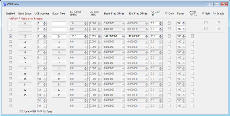
                    recently a Heathkit SB-1000 amplifier in the 1990's,
                    this was my first kit that required using a
                    magnifying lens to identify the component values.
                    Confirming the value of each of these little
                    components and finding its mounting holes on the
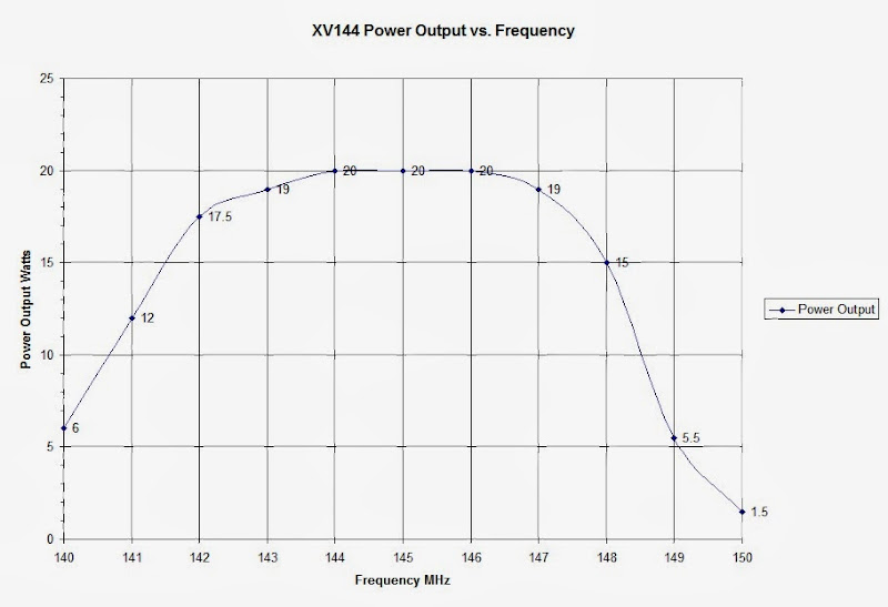
                    printed circuit board reminded me of the times I've
                    played the old "Where's Waldo?" game over
                    and over!

8. One of the kit's 0.01 μF monolithic capacitors. Having built a Heathkit HW-101 in the 1970's and most recently a Heathkit SB-1000 amplifier in the 1990's, this was my first kit that required using a magnifying lens to identify the component values. Confirming the value of each of these little components and finding its mounting holes on the printed circuit board reminded me of the times I've played the old "Where's Waldo?" game over and over!

3 May
                    2012 - I spent 2 more hours building the Elecraft
                    XV144 tonight and reached the end of page 34 of the
                    assembly manual. The IF bandpass inductor L17 was
                    not installed as it was defective and awaiting
                    replacement. This is my RF board after 9 hours total
                    assembly time.

9. 3 May 2012 - I spent 2 more hours building the Elecraft XV144 tonight and reached the end of page 34 of the assembly manual. The IF bandpass inductor L17 was not installed as it was defective and awaiting replacement. This is my RF board after 9 hours total assembly time.

L17, one of the IF bandpass filter inductors,
                    was defective. The ferrite tuning slug was bound so
                    tightly that it cracked while attempting to loosen
                    it.

10. L17, one of the IF bandpass filter inductors, was defective. The ferrite tuning slug was bound so tightly that it cracked while attempting to loosen it.

Another view of the IF bandpass filter inductor
                    L17.

11. Another view of the IF bandpass filter inductor L17.

5 May
                    2012 - I worked 3 more hours today and finished to
                    page 43 of the assembly manual. I am awaiting the
                    replacement L17 so I can mount this board to the
                    bottom cover and complete the assembly. 12 hours
                    assembly time at this point.

12. 5 May 2012 - I worked 3 more hours today and finished to page 43 of the assembly manual. I am awaiting the replacement L17 so I can mount this board to the bottom cover and complete the assembly. 12 hours assembly time at this point.

Here
                    is a close up of T1. For those who suffer
                    inductophobia, you can buy one of these pre-wound by
                    AA3WF for $19.00. I can't imagine someone hesitating
                    to wind this transformer after having accomplished
                    all the detailed building to this point.

13. Here is a close up of T1. For those who suffer inductophobia, you can buy one of these pre-wound by AA3WF for $19.00. I can't imagine someone hesitating to wind this transformer after having accomplished all the detailed building to this point.

Here
                    is a close up of the $50 XVOVN crystal oven option.

14. Here is a close up of the $50 XVOVN crystal oven option.

7 May
                    2012 - The replacement L17 arrived today. I was
                    impressed with Elecraft service's prompt response to
                    my request! Here is the completed Elecraft XV144
                    transverter with the top cover removed after 13
                    hours total assembly time from start to finish.

15. 7 May 2012 - The replacement L17 arrived today. I was impressed with Elecraft service's prompt response to my request! Here is the completed Elecraft XV144 transverter with the top cover removed after 13 hours total assembly time from start to finish.

Here is the front panel of the completed XV144
                    transverter kit.

16. Here is the front panel of the completed XV144 transverter kit.

A
                    view of the rear panel.

17. A view of the rear panel.

I
                    placed an N male to BNC female adapter on the
                    antenna connector as I use BNC coaxial cable jumpers
                    in my station.

18. I placed an N male to BNC female adapter on the antenna connector as I use BNC coaxial cable jumpers in my station.

Frequency Stabilization

Together with the crystal oven option, a SilenX
                    Ixtrema Pro 40mm x 10mm 14dBA 5 cfm fan secured with
                    double-sided foam tape over the vent holes in the
                    top cover stabilized the temperature and frequency
                    control of the Elecraft XV144 transverter
                    sufficiently for WSPR operation on 144.490500 MHz.

19. Together with the crystal oven option, adding a SilenX Ixtrema Pro 40mm x 10mm 14dBA 5 cfm fan secured with double-sided foam tape over the vent holes in the top cover improved the temperature and frequency stability of the Elecraft XV144 transverter for WSPR operation on 144.490500 MHz.

Exposed temperature sensitive components in
                    the Elecraft XV144 transverter 116 MHz Local
                    Oscillator: slug tuned L19 at 10 o'clock from
                    Isotemp crystal oven; Q1, C12 (behind Q1), C14 and
                    L4 (at 3 o'clock next to crystal oven)

20. Exposed temperature sensitive components in the Elecraft XV144 transverter 116 MHz Local Oscillator: slug tuned L19 at 10 o'clock from Isotemp crystal oven; Q1, C12 (behind Q1), C14 and L4 (at 3 o'clock next to crystal oven)

A
                    wad of cotton is in place around all the exposed
                    temperature sensitive components of the Elecraft
                    XV144 transverter 116 MHz Local Oscillator. Sterling
                    Coffey NØSSC demonstrated this frequency
                    stabilization technique on
                    http://www.youtube.com/watch?v=wXkhsfEDIok

21. A wad of cotton is in place around all the exposed temperature sensitive components of the Elecraft XV144 transverter 116 MHz Local Oscillator. Sterling Coffey N�SSC demonstrated this frequency stabilization technique on http://www.youtube.com/watch?v=wXkhsfEDIok

A 1.5 cm high by 5 cm dia. styrofoam cover
                    for the Elecraft XV144 local oscillator circuit was
                    cut from the bottom of a disposable cup.

22. A 1.5 cm high by 5 cm dia. styrofoam cover for the Elecraft XV144 local oscillator circuit was cut from the bottom of a disposable cup.

The
                    styrofoam cover was placed over the cotton ball
                    surrounding the Elecraft XV144 Local oscillator
                    components. The purpose was to pack the cotton and
                    to further prevent air circulation around the
                    components.

23. The styrofoam cover was placed over the cotton ball surrounding the Elecraft XV144 Local oscillator components. The purpose was to further thermally insulate the local oscillator circuit.

24. Data from WSPR frequency stability test with the styrofoam cup LO cover. At first, a loose wad of cotton was around the local oscillator components. At 0400 UTC on 24 June, the styrofoam cover was placed over the cotton and local oscillator components. The diurnal frequency variation corresponds with room temperature that varies between 73� F and 78� F. The smaller oscillations represent short term thermal cycling. The graph shows no apparent effect on the day-night frequency variation, but the smaller oscillations are denser and suggest improved short term stability with the styrofoam cover.  Further stabilization would require using an external synthesizer such as the VHF apolLO controlled by a rubidium or GPS frequency standard.

GPS Disciplined Oscillator

Glenn Elmore N6GN engineered this GPS
                      disciplined frequency reference for selected
                      stations in our West Coast VHF/UHF WSPR Study
                      Group. It provides a 10 MHz reference as well as a
                      GPS disciplined substitute for the master
                      oscillator or local oscillator of various
                      commercial transceivers or transverters.

25. Glenn Elmore N6GN engineered this GPS disciplined frequency reference for selected stations in our West Coast VHF/UHF WSPR Study Group.  This version provides a +5 dBm 10 MHz reference for the Flex-1500 as well as a +10 dBm GPS disciplined 116 MHz substitute for the local oscillator of the XV144 transverter.  The discussion thread can be read here.

The GPS active antenna has a clear view of
                      the sky, magnetically secured to a steel lumber H3
                      Hurricane Tie plate on an awning upright.

26. The GPS active antenna has a clear view of the sky, magnetically secured to a steel lumber H3 Hurricane Tie plate on an awning upright.

A typical Elecraft XV144 transverter
                      modification for the GPS10V frequency reference.
                      The 47Ω resistor suppresses the 116 MHz crystal
                      oscillations and the oscillator transistor Q1 now
                      functions to amplify the external 116 MHz
                      reference signal.

27. A typical Elecraft XV144 transverter modification for the GPS10V frequency reference. The 47Ω resistor suppresses the 116 MHz crystal oscillations and the oscillator transistor Q1 now functions to amplify the external 116 MHz reference signal.

Elecraft XV144 Auxiliary BNC connector J8 is
                      only used if the transverter is optionally wired
                      for separate transmit and receive 144 MHz antenna
                      connections. I connected a length of RG-174/U 50
                      ohm miniature coaxial cable to the unused J8 for
                      the GPS disciplined 116 MHz reference signal.

28. Elecraft XV144 Auxiliary BNC connector J8 is only used if the transverter is optionally wired for separate transmit and receive 144 MHz antenna connections. I connected a length of RG-174/U 50 ohm miniature coaxial cable to the unused J8 for the GPS disciplined 116 MHz reference signal.

The .01 μF capacitor and 47 Ω resistor are
                      soldered across R5 and the RG-174/U cable
                      connected across the 47 Ω resistor.

29. The .01 μF capacitor and 47 Ω resistor are soldered across R5 and the other end of the RG-174/U cable connected across the 47 Ω resistor.

The Elecraft XV144's internal local
                      oscillator with crystal oven option had exhibited
                      3-4 Hz frequency drift during 2 minute WSPR
                      transmissions and long term frequency instability
                      with ambient temperature variation. This frequency
                      instability and drift was eliminated with the
                      GPS10 frequency reference.

30. The Elecraft XV144's internal local oscillator with crystal oven option had exhibited 3-4 Hz frequency drift during 2 minute WSPR transmissions and long term frequency instability with ambient temperature variation. This frequency instability and drift was eliminated with the GPS10 frequency reference.

Exciter Setup

My Transverter Setup in PowerSDR (Alt-X) for
                      the Elecraft XV144. The LO Error will vary for
                      your setup and adjusts the Flex 1500 frequency
                      readout to a known standard on 2 meters. Not
                      having a precision signal generator, this is how I
                      calibrated the XV144 Local Oscillator. First I
                      calibrated the Flex 1500 precisely to WWV, then
                      tuned my other 10 meter transmitter precisely to
                      29.000 MHz as measured on the Flex 1500 receiver.
                      While transmitting a CW signal on 29 MHz (very low
                      power is sufficient) I coarsely tuned the Flex
                      receiver to its 5th harmonic on 145.000 MHz with
                      L19, then fine tuned for zero beat with the LO
                      Error adjustment. I set the RX Gain to the nominal
                      25 dB conversion gain as stated in the XV144
                      specifications. This gave a near S1 meter reading
                      on receiver background noise. The XV144 receives
                      and transmits according to specifications within
                      144-146 MHz range. It does work beyond that range
                      (and on MARS frequencies) with some reduction in
                      transmitter power and receiver sensitivity.

31. My Transverter Setup in PowerSDR (Alt-X) for the Elecraft XV144. The LO Error should be 0.000 kHz when using the GPS disciplined frequency reference.  Otherwise, the LO Error will vary for your setup and adjusts the Flex 1500 frequency readout to a known standard on 2 meters. Not having a precision signal generator, this is how I calibrated the XV144 Local Oscillator. First I calibrated the Flex 1500 precisely to WWV, then tuned my other 10 meter transmitter precisely to 29.000 MHz as measured on the Flex 1500 receiver. While transmitting a CW signal on 29 MHz (very low power is sufficient) I coarsely tuned the Flex receiver to its 5th harmonic on 145.000 MHz with L19, then fine tuned for zero beat with the LO Error adjustment. I set the RX Gain to the nominal 25 dB conversion gain as stated in the XV144 specifications. This gave a -130 dBm reading on receiver background noise level at 1 kHz bandwidth. (For accurate RxGain adjustment refer to "Signal Level Measurement with PowerSDR and External Transverters.") The XV144 receives and transmits according to specifications within 144-146 MHz range. It does work beyond that range (and on MARS frequencies) with some reduction in transmitter power and receiver sensitivity.

The
                    PowerSDR Antenna Selection Form is set in Expert
                    Mode here for Separate Transmit and Receive RF
                    Connections to the transverter.

32. The PowerSDR Antenna Selection Form is set in Expert Mode here for Separate Transmit and Receive RF Connections to the transverter.

On the Air Test

33. 8 May 2012 - I finally applied power and aligned the transverter. Here the FlexRadio 1500 is driving the Elecraft XV144 Transverter to 15 watts output on CW.

34. Monitoring KJ6KO's 2 meter beacon (CM88ws) with my Flex 1500 and Elecraft XV144 transverter. The receiving antenna at grid square CM98iq was an Arrow OSJ 146/446 J-Pole at 20 feet.

25
                    May 2012 - I erected a pair of stacked halo
                    antennas. Details at
                    http://www.qsl.net/kp4md/144_mhz_halo.htm

35. 25 May 2012 - I erected a pair of stacked halo antennas. Details at http://www.qsl.net/kp4md/144_mhz_halo.htm

TransmitterOutput Power as measured into a
                      non-reactive 50 ohmdummy load after alignment per
                      the instruction manual.The Input Attenuation
                      Adjustment, R22, was set for 20watts maximum
                      output with the Flex 1500 set to 100%drive level
                      from 144-146 MHz. R22 may be adjusted for20 watts
                      output on other frequencies, but this wouldpermit
                      operation beyond the safe power limit withinthe
                      144-146 MHz range.

36.  Transmitter Output Power as measured into a non-reactive 50 ohm dummy load after alignment per the instruction manual. The Input Attenuation Adjustment, R22, was set for 20 watts maximum output with the Flex 1500 set to 100% drive level from 144-146 MHz. R22 may be adjusted for 20 watts output on other frequencies, but this would permit operation beyond the safe power limit within the 144-146 MHz range.

KP4MD 144 MHz STATION SUMMARY

  • Exciter: FlexRadio 1500
  • Transverter: Elecraft XV144
  • Transmitter Power Output: 5 watts (37 dBm) or 10 watts (40 dBm)
  • Amplifier: RM Italy KL-145 or Mirage B-2518-G
  • Amplifier Power Output: 50 watts (47 dBm) or 100 watts (50 dBm)
  • Transmission Line: 35 feet of Times Microwave LMR-400 coaxial cable. Attenuation: 0.5 dB
  • Antennas: 2 stacked 144 MHz halos at 14 and 18 feet. Gain: 7.88 dBi
  • Effective isotropic radiated power: 274 watts (53 dBm) or 547 watts PEP (57 dBm)
  • Typical receiver noise floor: -162 dBm/Hz
Return to KP4MD Home Page
Top