Club callsign MS0FNR    

On the Workbench

of the Caithness Amateur Radio Society.


Brian's latest project.

A RACAL TRA950 radio telephone.


Crystal controlled on 11 transmit and 23 receive frequencies. 50w low power, 120w high power.

Modes: SSB (A3J), SSB reduced carrier (A3A), and Compatible AM (A3H).

All solid state except for a pair of TT22 valves in the PA

Using a QRPlabs "ProgRock2" to generate frequencies for 3615KHz operation as crystals no longer available.

Cant' find a manual/schematic anywhere!!


More on Simon's CR100 rebuild.

Simon is gradually working his way through the rebuild where he is repainting and rewiring.

Click on the links for pictures of the items:-


The chassis.


Coil pack and IF transformers.


Variable capacitor.


Tagboards.


You can see Simon on YouTube HERE.


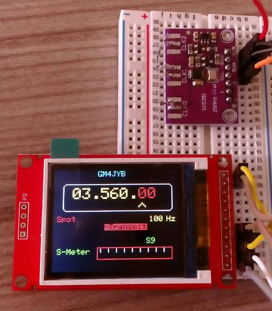
IC-765 repair for club member.

Hamish carried out the repair and here is his description:-

A Club member sent me his Icom 765 rig that had stopped working. When he switched on the dials shone very bright and then the entire radio went dead.
This sounded like a voltage surge from the power supply or some other very big spike.

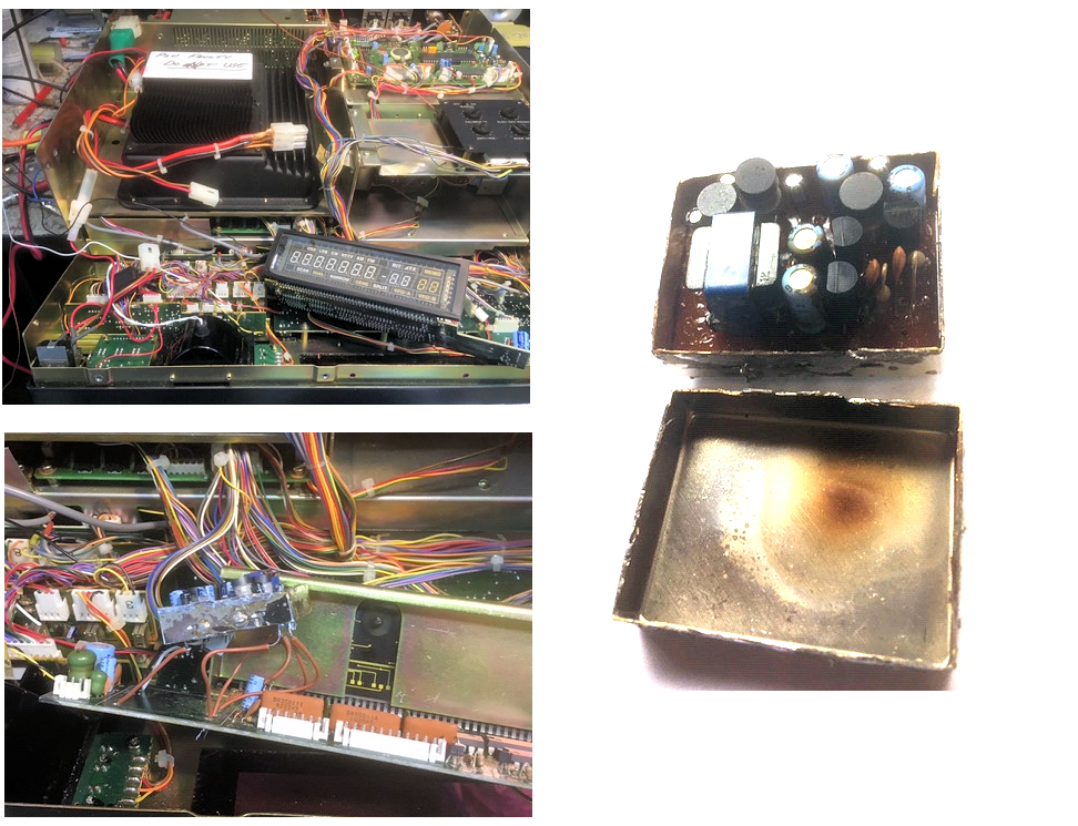
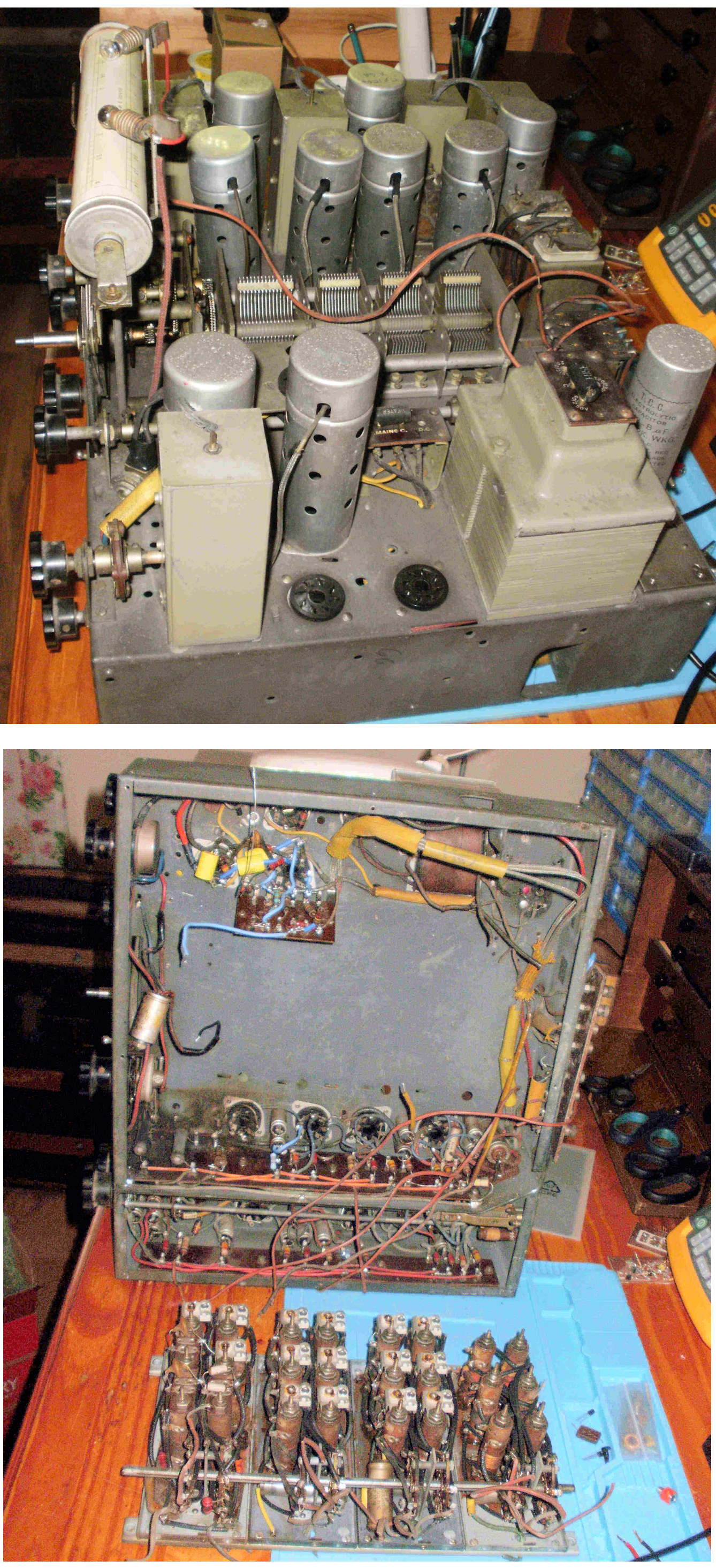
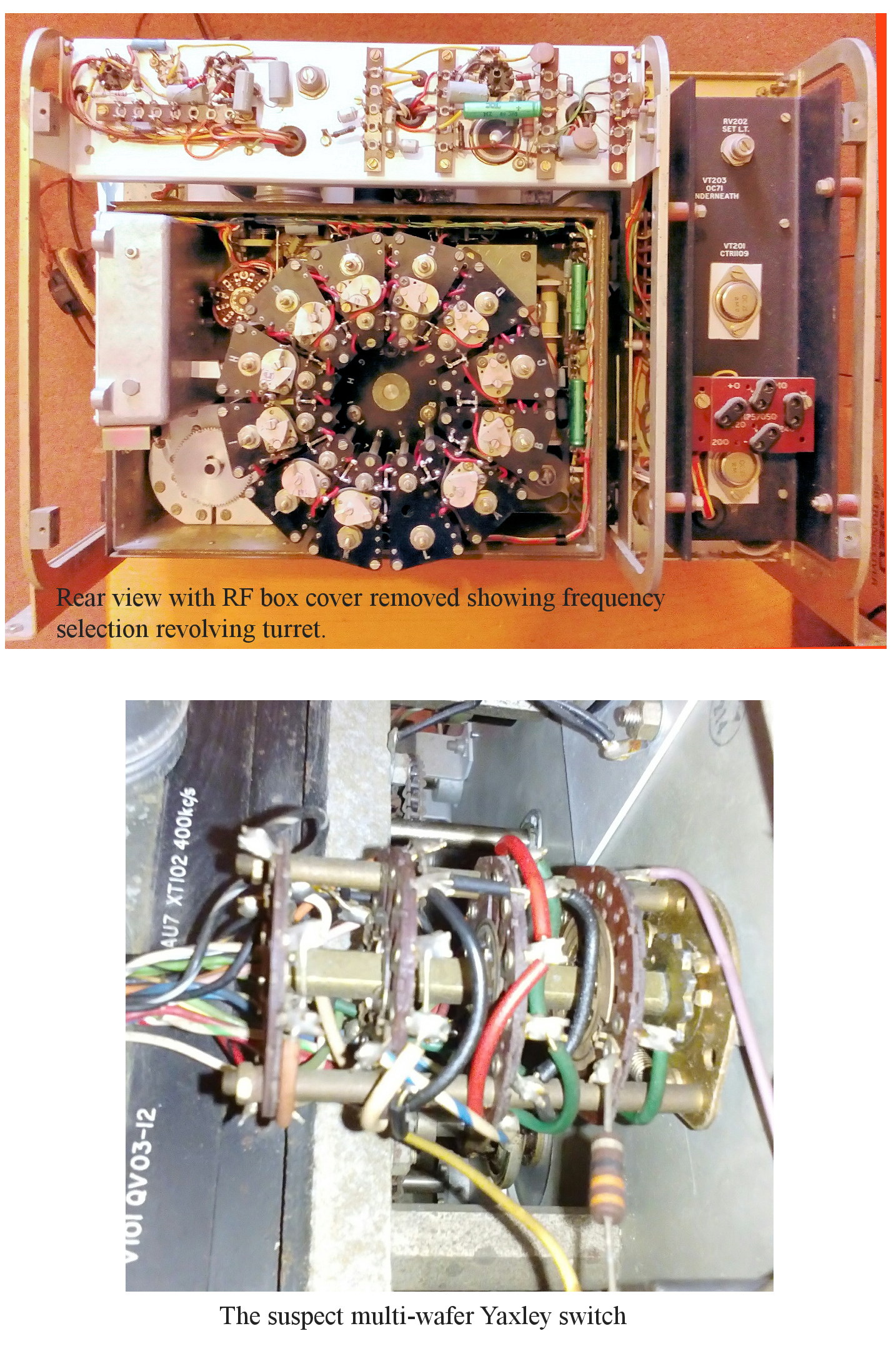
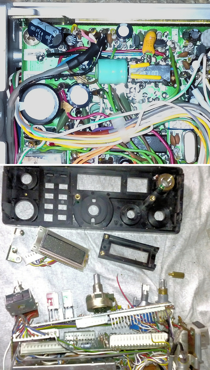
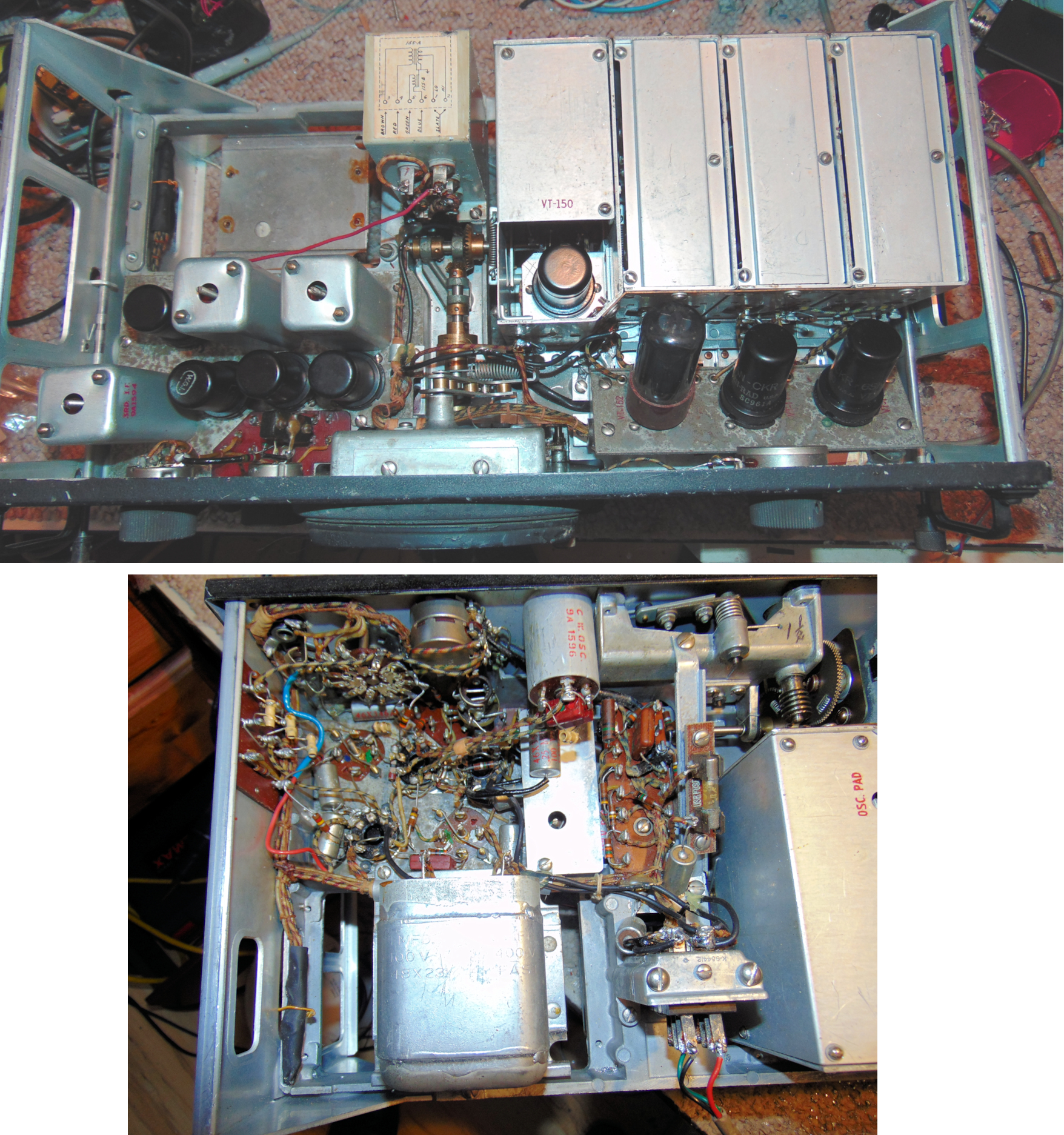
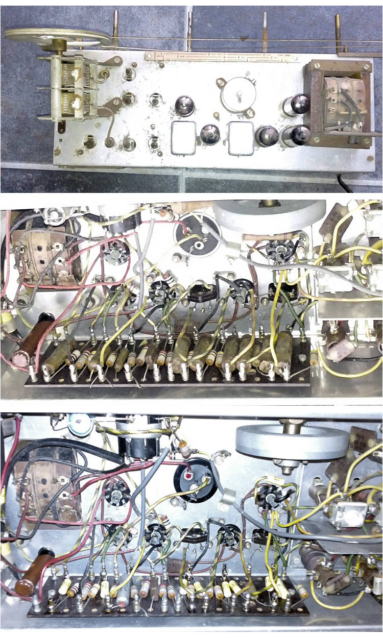
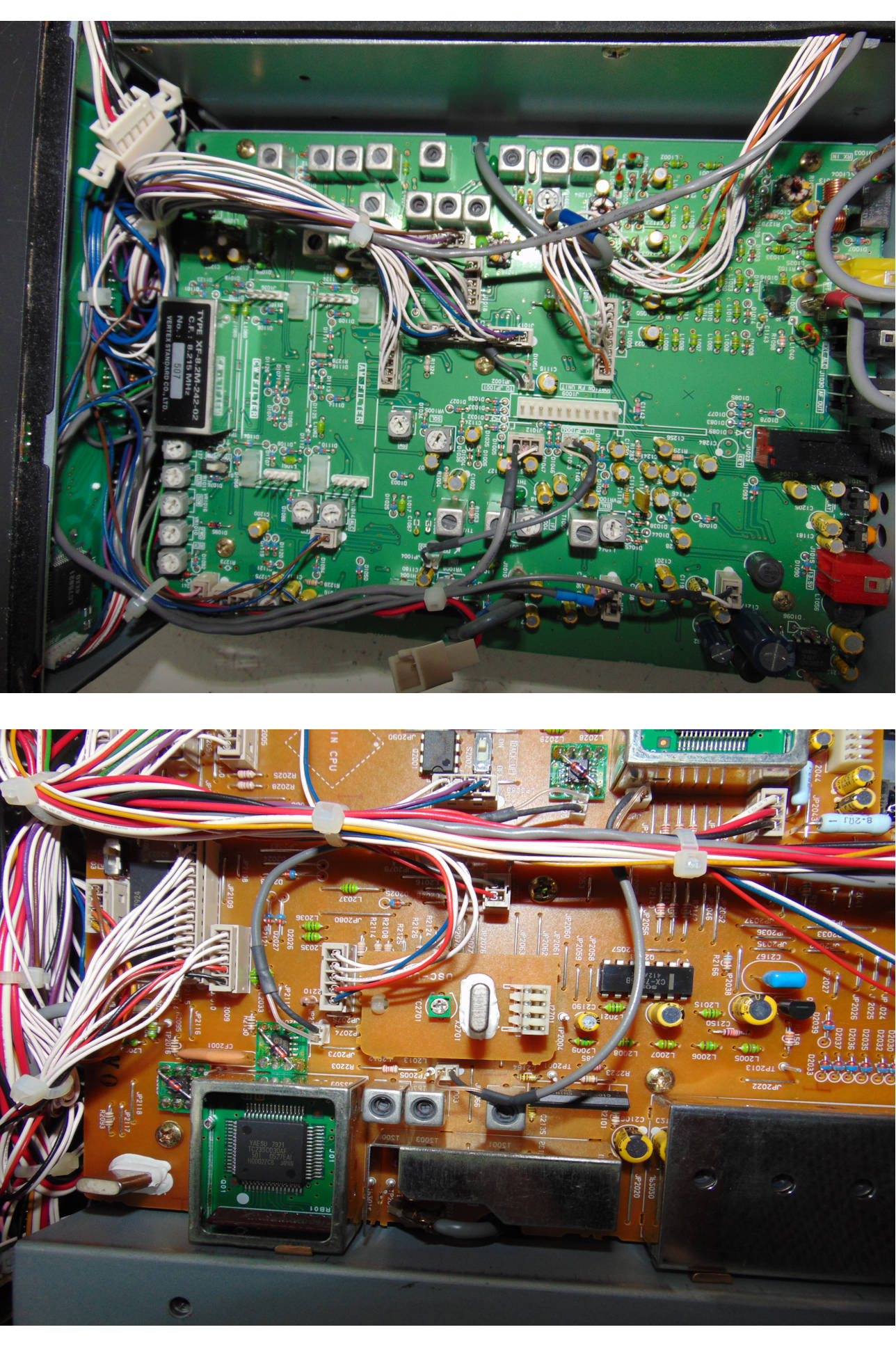
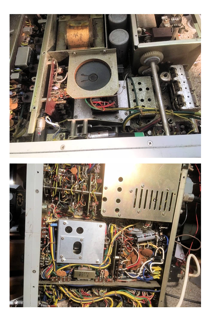
Like all these type of rigs it involves loads of screws being removed to get inside. 
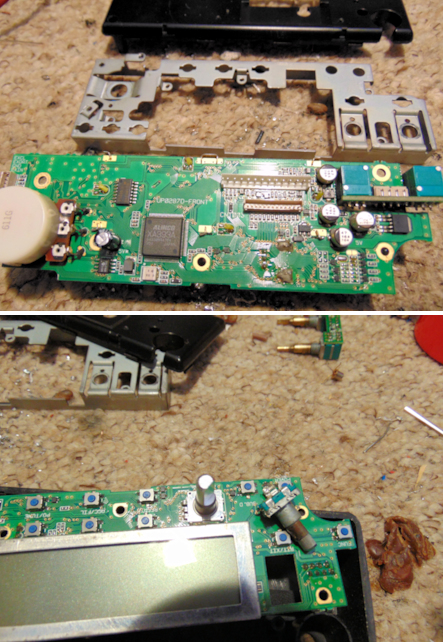
As the display was dead, I had to remove the front panel to gain better access to the display module. I was fairly soon able to establish that several voltages were now missing.
The circuit showed an IC3 as the source of the missing voltages, however it did not at all match the standard appearance of an IC. 
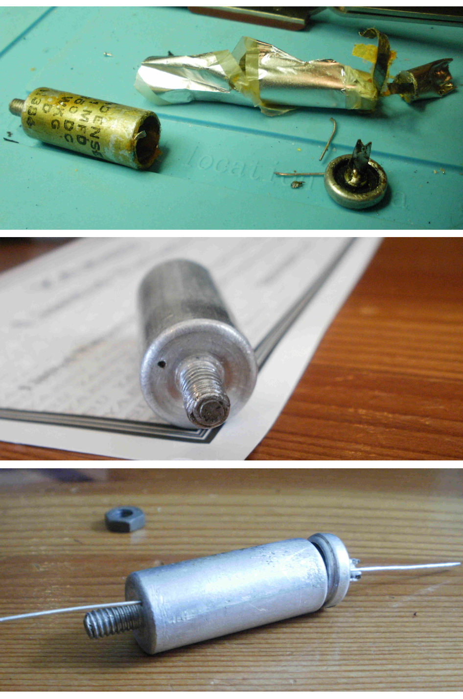
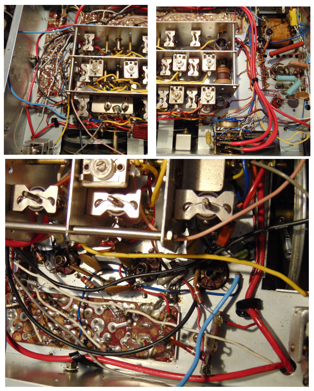
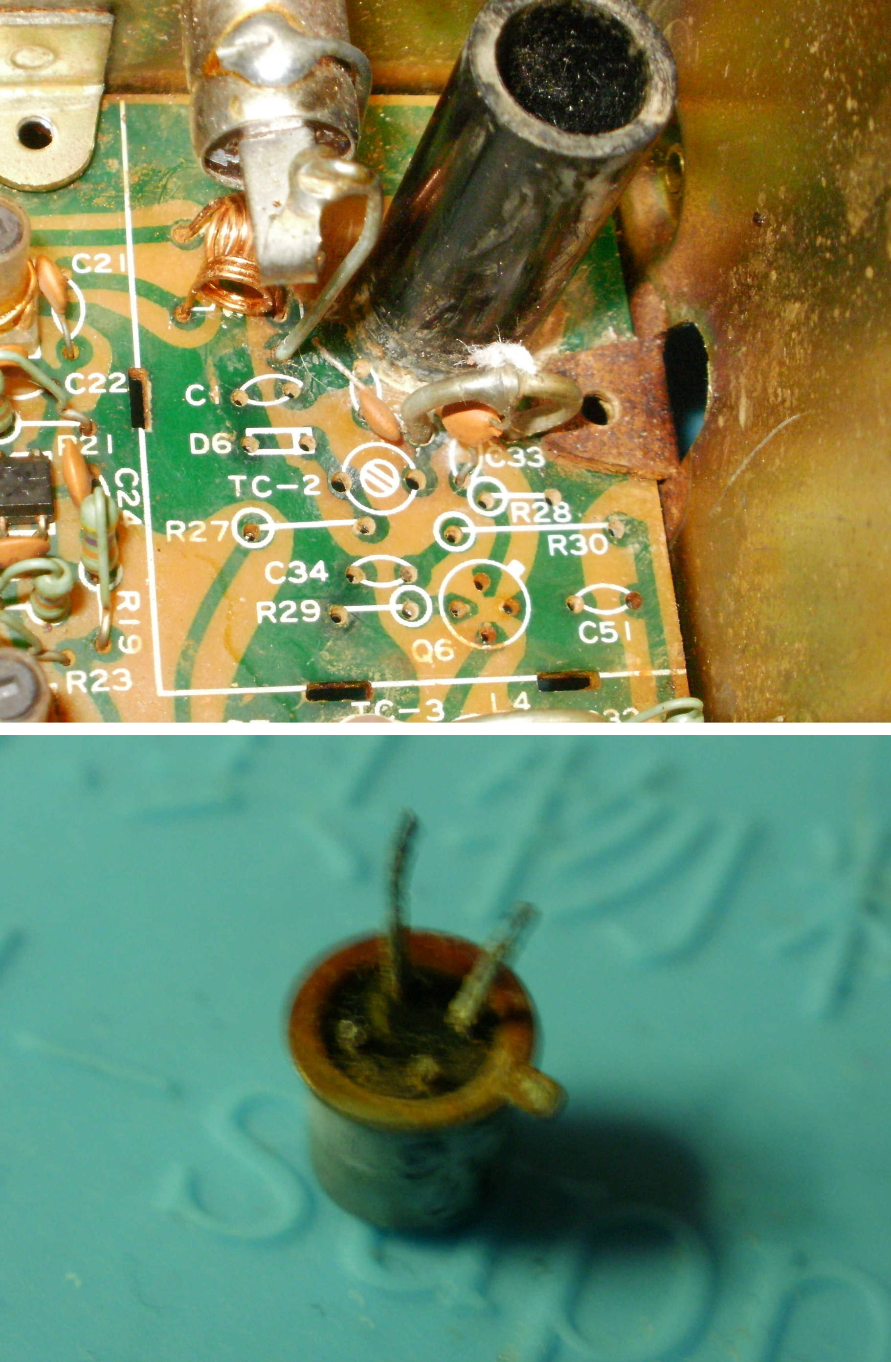
This unit is a 45mm.. X 35 mm X 18mm chromed brass sealed welded box.

I contacted several dealers, main agents and eventually Icom, only to discover that this component was original bespoke supply by a company no longer making these, so it was just not available.
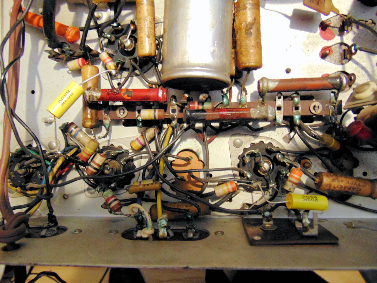
Not liking the idea of not being able to repair the rig I cut open the metal box to find it had a bunch of standard components in the form of a DC-DC inverter inside. Further investigation indicated two open circuit transistors so I thought I may have suitable replacements. However there are no equivalent transistors so I placed an order with Cricklewoods but then waited about 12 weeks for these to be delivered as sourcing was a problem.
When these arrived I was able to repair and test the unit, solder the case back together, make and fit new connection pins to refit the unit.

Everything switched on and worked as it should with the voltages all correct so I closed up the rig, about 45 screws, and it is now back with the owner.

I had loaned him a rig during the period we had to wait for these transistors. However I wonder if there are more of these rigs discarded due to an IC not being available and the unit looking just unrepairable.
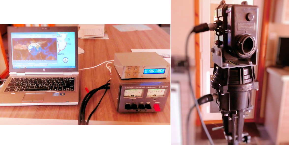
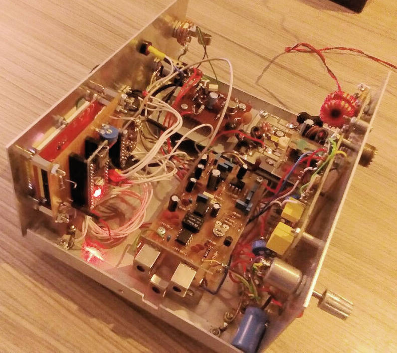
The photos will give you an idea as to what was involved.


More pictures can be seen can be seen by clicking on the image.


More on Simon's CR100 project.

He has been attacking the caps.

All the old tubular paper capacitors are known to be problematic. Simon has stripped out the old internal gubbins and placed new capacitors within the tubes. The pictures show some of the process.

In a nutshell, the tube is cut open, the old foil is removed and a small hole is drilled in both ends. The new capacitor is placed within the tube with the leads poking out either end. On the nut end the lead is wrapped around the thread. On the connector end the lead is soldered onto the terminal


More pictures can be seen can be seen by clicking on the image. See his YouTube description here:-

https://www.youtube.com/watch?v=KsXwR7ExJK8


Simon's CR100 project.

Simon received this in the partially stripped down state from Hamish and has set to work with the renovation.

Details of the set from the "History of Science Museum":-
The CR100 was a high grade HF receiver primarily used for fixed services, with frequency coverage of 60kHz-30MHz. Several versions of the CR100 were produced, starting with the prototype, CR100, and continuing with models designated CR100/1 through CR100/8. The CR100/1, CR100/4-CR100/8 were also called the Admiralty Model B28 receivers. 'Admiralty Pattern B28' was the standard MF/HF receiver on the Royal Navy and Royal Canadian Navy ships in World War II. CR100 sets were at the cutting edge of technology when produced in the late 1930s and 1940s.


More pictures can be seen can be seen by clicking on the image. See his YouTube description here:-

https://www.youtube.com/watch?v=KsXwR7ExJK8


Brian Working on Signal Generator.

Ex Hamish's Marconi TF144H/4S. Passed on to Brian. In his own words:-

I received the sig-gen in sort-of-working state. It is for CW/AM from 10KHz to 72MHz. Problems were a low and unstable indicated output and very crackly into heaphones on the crystal-calibrate position.

A few days were spent sorting things out. Two open circuit resistors found but most were okay. One leaky capacitor found and replaced but all others okay. An open circuit thermistor stopped the Wein Bridge modulator working. This was replaced with a variable resistor and critically adjusted as thermistors of the type required (Type A15) are virtually unobtainable now. The mode setting switch, a multi wafer Yaxley type was flashing over in one position. Switch cleaner didn't help so the wiring was re-configured to take the high voltage off the switch. It doesn't flash over now but the switch is still a bit suspect. There is also a multi-wafer Yaxley switch inside the RF box which was given a touch of switch cleaner/lubricant.

The generator works reasonably well now although the output indicator reads low on the HF ranges but my oscilloscope says otherwise!


More pictures can be seen can be seen by clicking on the image.


Chris's Quadrifilar Helix Antenna.

Chris is interested in downloading weather images from the Meteor M2 satellite.

More info on the satellite can be seen here:-

http://www.wmo-sat.info/oscar/satellites/view/meteor_m_n2

Although he was using a 2m antenna he has made this QFH one which is designed for the satellite frequency of 137MHz. It works well and has the advantage of being omni-directional with circular polarization which is ideal for the satellite.


A closer view of the antenna and a screen view of the satellites signal can be seen by clicking on the image.


Simon's VHF Antenna Matching Unit

Simon's antenna for 2metres is one he obtained and wanted to connect it to his FT-897 rig.

He had some balanced feeder that he wanted to use but the rig is designed for co-ax. Also the Yagi antenna is of unknown impedance.
To connect the two he built himself a simple matching unit.

These are pictures of his successful efforts. It shows the internals and the unit boxed up and by the side of his rig.


The Club's satellite project.

The club has bought some satellite equipment for use in demonstrating and hopefully inspiring others in the use of satellites in amateur radio.

The kit consists of a Yaesu G-5500 azimuth and elevation rotator and control box for pointing the antenna at a target as it passes. There is also an interface to connect the control box to a computer for tracking control. This is a Fox Delta ST2 which connects to the computer via RS232.
We are using one of the clubs newly purchased laptop computers plus a USB to RS232 cable. The computer is loaded with the SatPC32 software to drive things.
There was also supplied two crossed Yagi antennas, one for 2m and the other for 70cm which have yet to be mounted on the system.

All we need now is a suitable 2m/70cm duplex radio (or two separate radios) so we can start experimenting and refining things.


Brians FT-290R project.

He says:-

The club has a couple of these 2 metre multimode rigs by donation. Because of the requirement for morse code practice it was decided that they might be useful for this despite their age (about 40 years!).
On examination, both of them had blown panel lamps, suffered from intermittent audio output and were off frequency.

The first one I chose to work on had an attached power amplifier which boosted the 2.5 Watt RF output to a massive 10 Watt. A lot of time was spent trying to sort out the audio problem. I came to the conclusion that the audio output chip was dying. This chip is an obsolete uPC575C2 now unobtainable. In my spares I had a TBA820 which gives the same level of output but is not pin compatable and a bit longer. However with a bit of persuassion, I got it to fit and the audio problem was cured.
Next the frequency error was corrected by adjustment of the PLL local frequency oscillator which had drifted.
Then the blown panel light was replaced which was a major operation entailing the total strip down of the front panel. I didn't have a replacement 3mm 12Volt bulb so, altough not entirely satisfactory, a white LED, with a series resistor, was used instead.
This rig is now good to go and the second one will be given the same treatment.


Click on picture for view of replacement amplifier IC and stripped down front panel.

<


Hamish finishing another project under lockdown.

He says:-

The BC348 is a american receiver dating from 1943 and was widely used in many aircraft.

It is all aluminium construction and very robust. This one has not been messed about, only the valve wiring slightly altered to use 6.3 heater volts instead of 28 volts. The dynamotor which provided HT volts has been removed and the radio now operates from an external power supply. which includes a speaker.

Very unusual to find one now in such good near unaltered condition.
If one sourced a dynamotor the radio could so easily be returned to its original design and operated from 28 volt DC batteries.

The earphones are also from the same era.


Click on picture for more photos.


From Hamish.

This time is is an Alinco DX70TH that is on the bench.

These rigs have an incremental rotary encoder, which is a fancy name for a multi mode selection knob, which had broken.

The rig has a front panel that is easily removed and only two ribbon connectors to take off and its free to work on. To fit the new part I had ordered did take quite a stripdown of the panel to remove the circuit board. Fairly simple job, the photos show the old and new part.

All back together and rig working as it should again.


Click on picture for the photos.


Brian at it this time!

His words:-

This is a domestic Bush AC-34 wireless set which came into my hands pleading for some TLC. Judging by the components inside, it was probably made in the mid 1950s.

On examination, it seemed all complete with a full complement of valves and good mains transformer. The vanes on the variable capacitor were bent so causing them to short, but this was remedied with a bit of gentle persuation.
It was slowly powered up and the valves all glowed nicely and there was HT voltage BUT no sound. The audio output tranformer was open-circuit! This is usually caused by the output valve taking too much current due to a leaking coupling capacitor feeding its grid, and this was the case here.

Most of the capacitors in this set were waxed paper and they are notorious for going leaky after many years of service/storage. They were all replaced and you can see from the picture the dead ones, all showing bad leakage, some less than 10Kohm.
The dead output transformer was temporarily replaced with a 240/9V mains transformer.

Power was applied again and the set sprang into life with reasonable alignment. I listened to Radio Scotland for about ten minutes ...... then silence! Investigations revealed that the frequency changer valve, a UCH42, was faulty and would only work for a short period of time before suddenly cutting out.
A replacement was sourced from Robin at Skirza, along with a correct audio output transformer. Having replaced these items, the set was switched on and now worked well with good audio and ample sensitivity.

The cabinet has had a hard life and showed evidence of lots of scrapes and knocks but was basically sound. After a bit of cleaning and polishing it now looks reasonable so is now my Long Wave, Radio-4 listening wireless in the conservatory.

Project complete.


Hamish at it again!

He says:-

This is a Trio 9R-59DS radio, it has band spread RF gain, antenna trimmer and BFO so it was aimed at both shortwave listening and amateur radio.
These are late 1960's radios and were very popular in the day. This one arrived working on two bands and silence after 12 MHz.

Opened it up and had a look around, lot of soldering been done and quite a number of unusual wires bridging parts of the radio IF section.
Changed the oscillator valve as this is the usual culprit when higher band stop working. Radio receiving poorly but working on all bands now.

Stripped out all obvious " modifications" found a couple of faults, diode soldered to wrong tag, cap on bfo wrong position, in other words restored to original circuit. Put in a voltage stabilizer valve. Powered up and now working much better that I remembered these to be.

I can understand now why it was so popular been listening to amateur bands with real good resolution of signals

Click on picture for internal views of the radio.


Another repair job from Hamish.

In his own words:-

Here is a domestic receiver Marconi T21A 1949-1950. Cabinet in very nice condition and the internals have never been touched. The owner wanted me to " have a look at it" as he wants to give it to his daughter as a keepsake. I assume it may have been in the family since new.
Powered it up with the usual light bulb in series and this did not indicate too much of a load. Soaked for a bit on Variac at 150 volts then later on full 240. Set has audio but too distorted to be of any use.

The bottom panel on most of these old sets is removable allowing access to the components. Output valve glowing red! checked grid volts and found 28 volts DC, should be near zero. Common fault on valve radios, capacitor linking output of previous stage to grid of output valve leaky. Replaced with new one and the audio is now very nice. Got a jolt off the Gram socket and found another capacitor more or less had become a resistor so replaced with new. Radio working great on all wavebands.
A simple repair this time.


Spiderbeam Mast


The club has taken delivery of three aluminium 12.5m masts from Spiderbeam

These will be used in demonstrations of Amateur Radio to Youth organisations. We were given a good discount from Spiderbeam who dealt with the order easily and with efficiency. Shipment from Germany was quick and without a hitch.

The top picture is of the masts as delivered, one has been opened showing the guying plates and hex wrench.

The lower left picture is of the substantial clamping arrangement and that on the right is of the mast in its lowered state.


The Club Mast


Les was unfortunate that his mast, supporting his 80, 40, 20m fan dipole, failed when a guy line became detached in heavy wind.

Because he is a stalwart of the RSGB club competitions and needed to get his aerials back up quickly, the recently refurbished club mast (see previous posting) was pressed into service.

Here you can see it in all its glory, supporting his temporary antenna, at his QTH.


Yaesu FT840
Hamish's next repair project. Here are his comments:-

"This is a spare Club rig that has decided to lose its RF output. Found it would TX for a few seconds and then drop to about 10 watts., unusual fault. Opened up and really could not see anything obvious.

Closer examination revealed what may be a sensor located on top of one RF output transistor had become detached, Could not find this sensor on the circuit diagram!! This was reattached with some silicon based heat resistant paste, but still only 10 watts output.

TX into dummy load, same result, started pooking around with my wooden prod and when pressing one of the output transistors the pa stage gave full power.
I was fairly obvious then that these was a poor contact so this was resoldered plus another joint that looked a bit suspect. Overdid it a bit with the solder flux and have ran out of cleaners.
Rig then worked correctly.

An " on air" test done with Les GM0TKB and John GM3JIJ Both said that all was well with the transmission."
Next project will be the dead antenna tuner that goes with the FT840

Click on picture for more images.


Brian's VFO Project - Update

Here is the Arduino driven VFO & display in the transceiver test bed. Managed to get the RIT working but the TX/RX switching using the Arduino too slow and unpredictable in CW. I had to resort to hardware switching. Also the rig is being used to try out a class E power amplifier. Still under development but not yet useable however at least the VFO and display work.


Simon's Pro2008 Scanner project

A small description of what had happened. ....

"This VHF UHF radio scanner I've had since the early 80s. I bought it second hand from a chap in Bower. It isn't the best scanner of its day. You can only store 8 channels. I hardly ever used it There being little activity on 2 meters in the 80s . (not even the Orkney repeater was thought of) Its been in the shed for many years and I took it out the other day and tried it. Well it powered up but didn't receive anything... not even from a signal generator. I opened it up and all around the input stage was a mass of rust. I removed all the components and screening in that area and cleaned up the board. The input transistor came out with only two legs ! Not surprising it was deaf. New UHF NPN transistor ordered so maybe I will put it back to into use."

Update
Simon has reported that the scanner has now been repaired and is available if anyone is interested.


Brian's VFO Project
Another Arduino project to create a VFO for a direct conversion transceiver. This was loosely based on a"sketch" by N6QW and provides the required frequencies with offsets and the display for the rig. It is based on a Arduino Nano driving a Si5351 synthesiser chip with a TFT OLED display. Almost finished but thinking of incorporating RIT (receiver incremental tuning). Will need to build a transmitter and a receiver board, along with a switching system to complete the project.


Skanti R5001 receiver.
This is one of Simon, GM8NYV 's, on-the-bench projects. Currently undergoing fault-finding.

Update
Various faults traced and rectified and replacement push button caps obtained for those missing. Radio works well and has now been sold


Yaesu FT201
Hamish's repair project. Here are his comments:-

"Radio was dead.
Transformer very hot.
The DC chain taking much to high current, 1200ma.
Investigation revealed two bad capacitors and a short circuit transistor in the oscillator board.
Better but still too high.
Checked the RF PA stage and found one tube had grid to cathode short.
Now correct voltages but had to do some frequency realignment.
Rig receiving real good with nice audio but needs a pair of PA tubes."

Update:- Hamish now has replacement valves installed and the rig was tested successfully on the air in a club net. Minor adjustments still required.

Final comments from Hamish:

"Two new old stock genuine original GEC tubed sourced and fitted. these were run on filaments alone for 10 hours and give an output of 140 watts, rig is being operated at 80-100 watts with good results reported on audio quality and stable on frequency. The rig is working great and been in use for three weeks but the next project waiting to go on the bench."

Click on picture for more images.


Kenwood TS-850 project..
Another of Hamish's projects from club member Sandy, 2M0FRR. Here is what he says:-

Sandy delivered the Rig to me last month and I set about seeing what was happening. Les, GM0TKB had advised me that these were prone to corrosion due to the factory location being near the coast.

The rig would TX but the mic gain was flat out and could not be reduced so massive overmodulation existed and the power was down quite a bit, I also noticed that the TX was off frequency from the RX.

Opened it up and eventually got at all the ribbon connectors, most were discoloured so I decided just to clean all 16 of them I then cleaned the ribbon sockets using calling cards soaked with switch cleaner then cleaned all the small plug connectors on the boards. Took a long time removing cleaning and reinstalling the circuit boards but eventually reassembled the rig and the result is very satisfactory, modulation under control and full 100 watts clean output, Rx and TX same frequency after small adjustment, so everything now works. However corrosion is difficult to stop and faults could appear in time.

Delivered the rig back to Sandy.

   Click on the picture for Hamish's video.


The Clubs Trailer Mast.
The Clubs mast undergoing a spot of refurbishment. The framework around the mast had become extremly corroded so needed to be replaced.

Click on the picture for a video.


Arduino Iambic Morse Keyer.
This is a lash-up of a simple morse keyer to investigate the Arduino, based on a project by by PA3HCM. It is simple and works!


80M Loop antenna.
Roddy and Martina pose proudly in front of their newly aquired 80m loop antenna.