![[tard]](pics/tard.jpg)
ANSI RF radiation dosage meter.
![[tard1]](pics/tard1.jpg)
Some designs are for research only. Advanced microwave and RF design skillz will be required to build these circuits.
This will show you how to add a bi-directional, 2.4 GHz amplifier to your Proxim Symphony for under $100. Bi-directional means you can mount the amplifier at the antenna to help overcome any cable loss, and the amplifier will automatically switch between receive and transmit modes. The cost is reduced by using readily available materials and components. Also, instead of a complicated RF sensing transmit/receive switch, a logic level indication of transmit is sent to the amplifier through a length of low cost coaxial cable. The final RF power output of this amplifier will be around +31 dBm (1.3 watts) and the receive gain is around 16 dB (with a 2 dB noise figure). If adapting for use on direct sequence spread spectrum systems, you'll want to lower the overall P1dB (+28 dBm or so) to keep the RF power amplifier in its linear region. To do this, attenuate the RF input power slightly.
Receive amplification is tricky subject. When done right, it works wonders. When done wrong, your stuck listening to shortwave broadcast stations in Yugoslavia. If you don't need to have the receiver amplifier (due to excess local noise/intermodulation or loss coax loss), just replace it with a stripline jumper. If you're too stupid to figure that out, then please don't build these.
Adaptation to wireless network cards other than the Proxim Symphony should be trivial.
Schematics
Most schematics are in their native Xcircuit PostScript format for ease of printing and modification. To use PostScript under Window$, you'll need to install the Ghostscript & Ghostview packages. Set Media to A2 for ease of viewing.
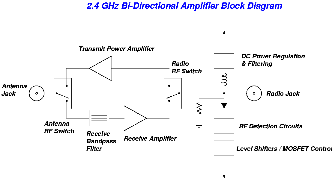
- 2.4 GHz Bi-Directional Amplifier Block diagram
- Bi-Directional 2.4 GHz Amplifier Schematic First original design - reference only - don't build
- Bi-Directional 2.4 GHz Amplifier Schematic Second original design - reference only - don't build
- Newest Bi-Directional 2.4 GHz Amplifier Design Includes an experimental idea for remote RF sense. Newest design - reference only - work in progress
- Bi-Directional 2.4 GHz Amplifier Using Pre-Built Modules and Evaluation Boards Untested - reference only
- Power Amplifier Only for PRISM2 Based Access Points Untested - reference only
Commercial Amplifiers
Here are some really nice commercial 2.4 GHz amplifiers.
- Sparco SP-BA24j 2.4 GHz Wi-Fi Signal Booster Nice idea with amp built into the antenna.
- Sparco SP-POE30-24 1000 mW Power Over Ethernet (POE) 2.4 GHz (802.11 b/g)
- RF LINX Amplifiers Sells multi-band amplifiers & converters.
FCC Records & Pictures of Commercial Amplifiers
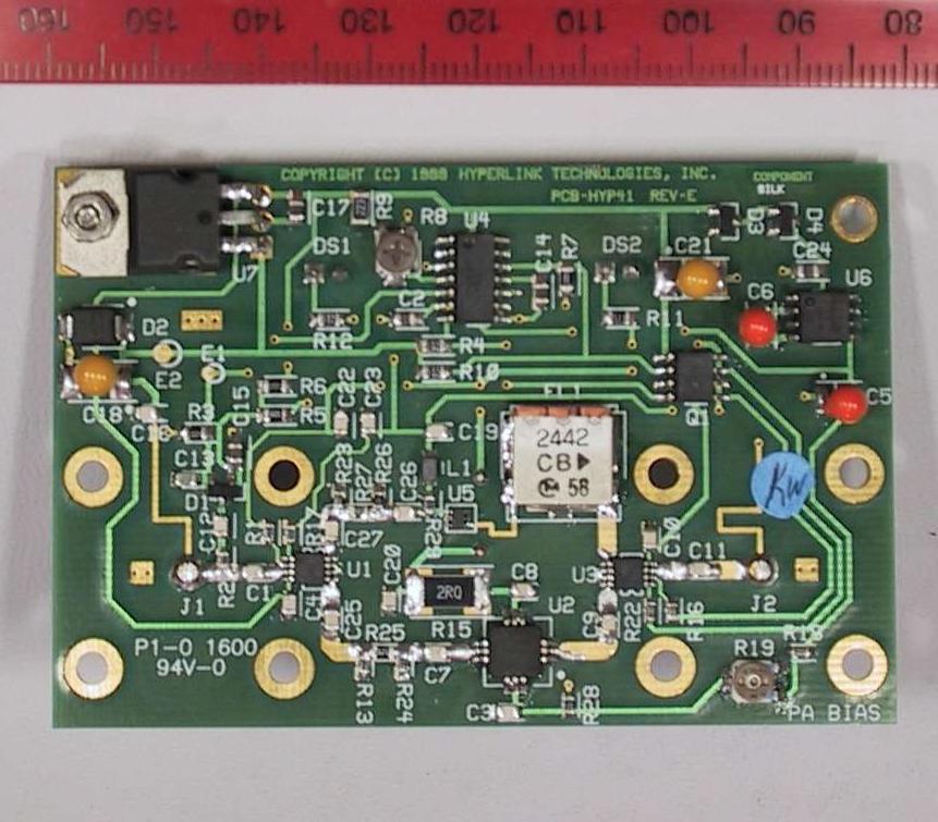
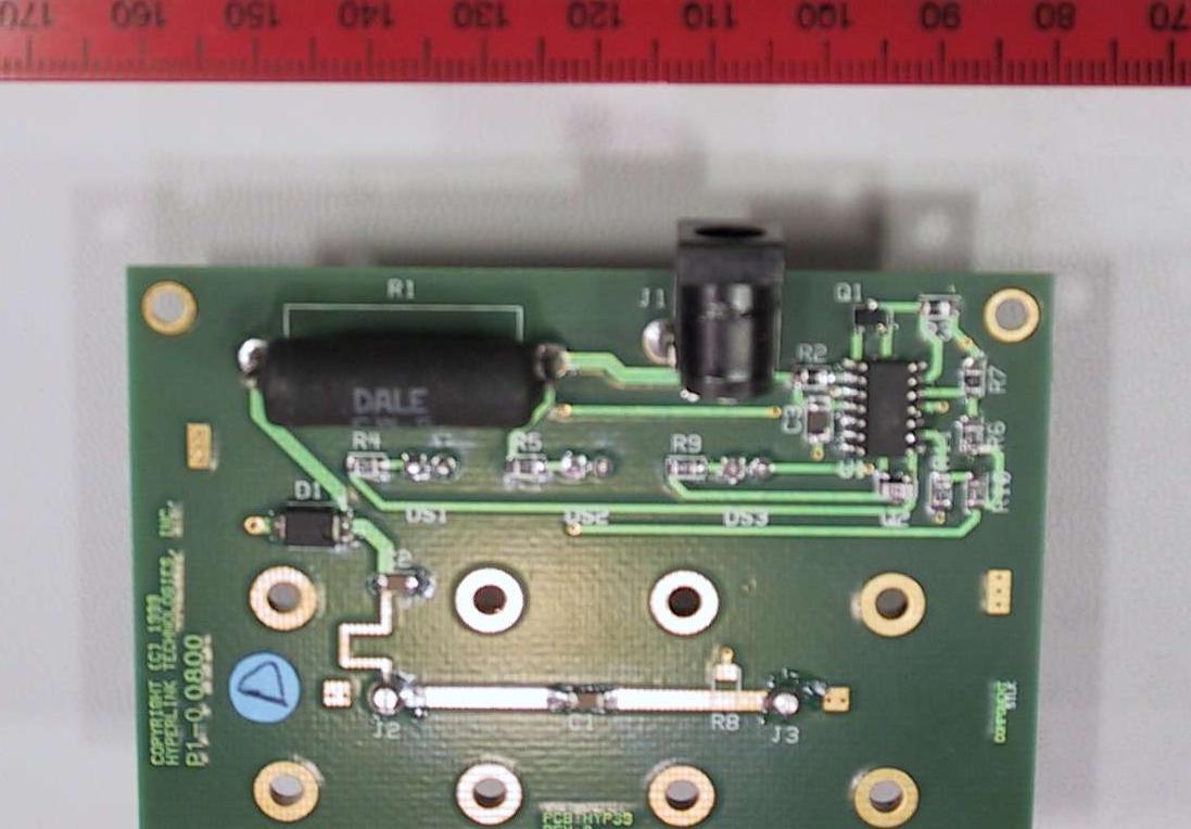
- Hyperlink - Pic 1
- Hyperlink - Pic 2
- Hyperlink PCB layout (20k PDF)
- Hyperlink amplifier block diagram (34k PDF)
- Breezecom 2.4 GHz amplifier FCC info Includes parts list!
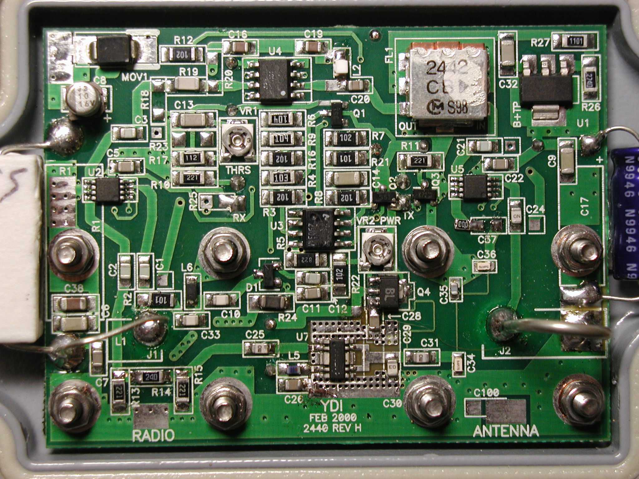
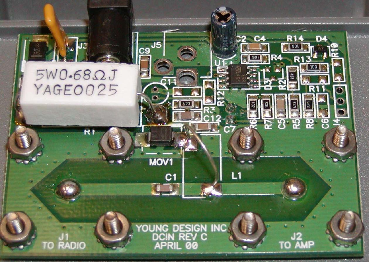
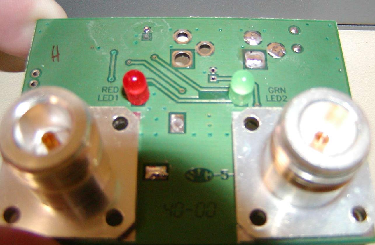
- YDI 2440 - Closeup
- YDI - Pic 1
- YDI - Pic 2
- YDI - Pic 3
- YDI - Pic 4
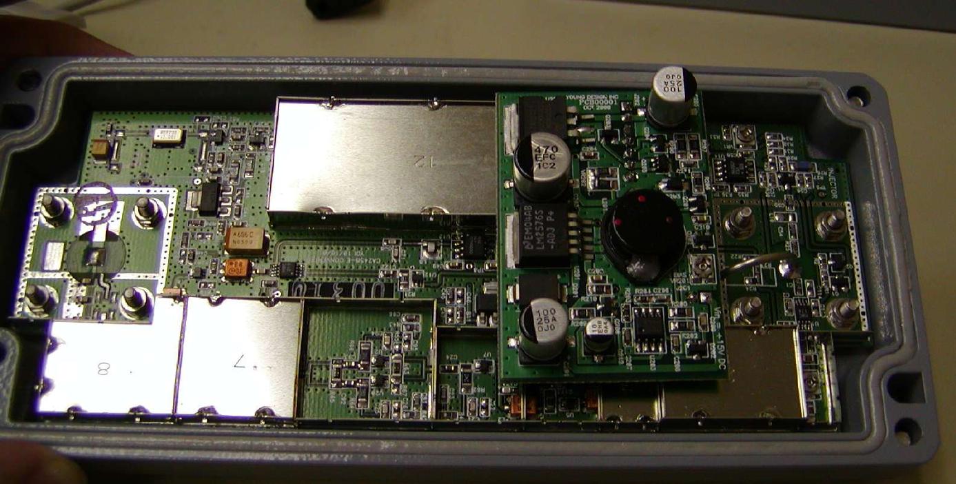
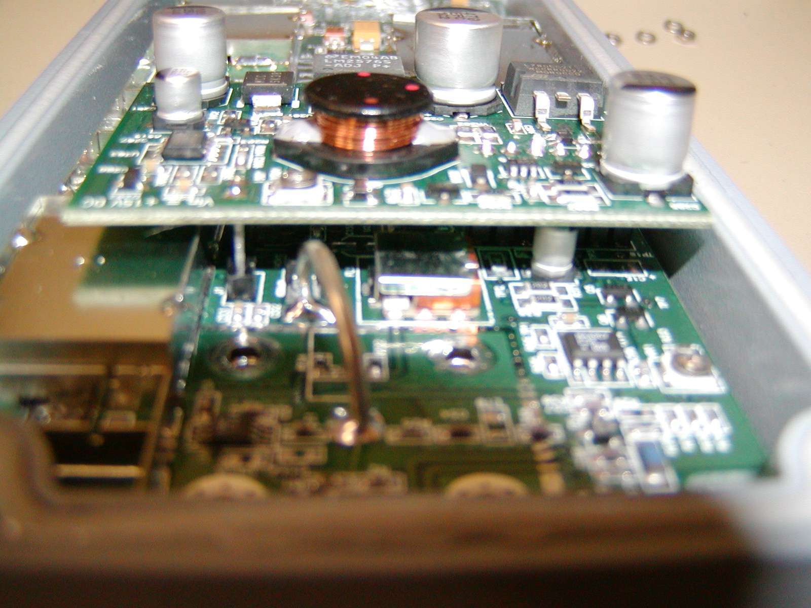
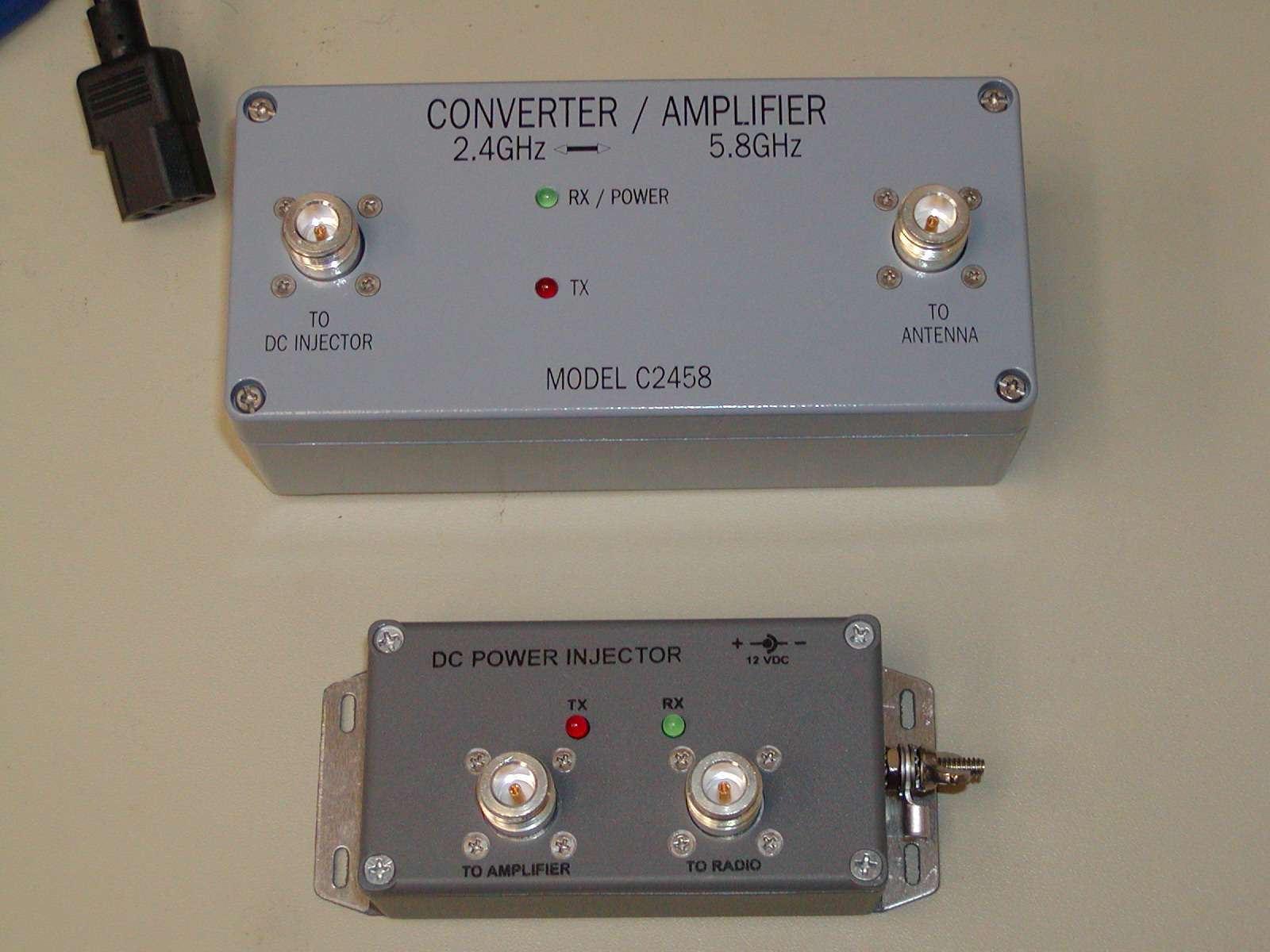
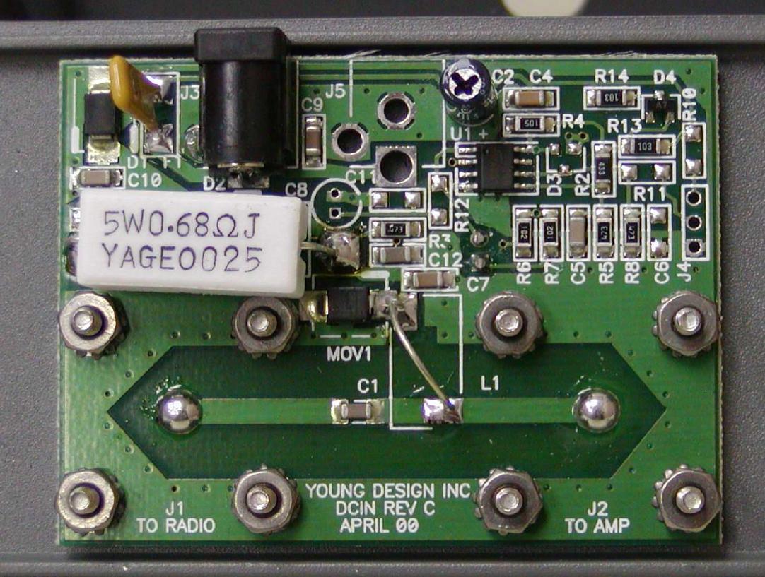
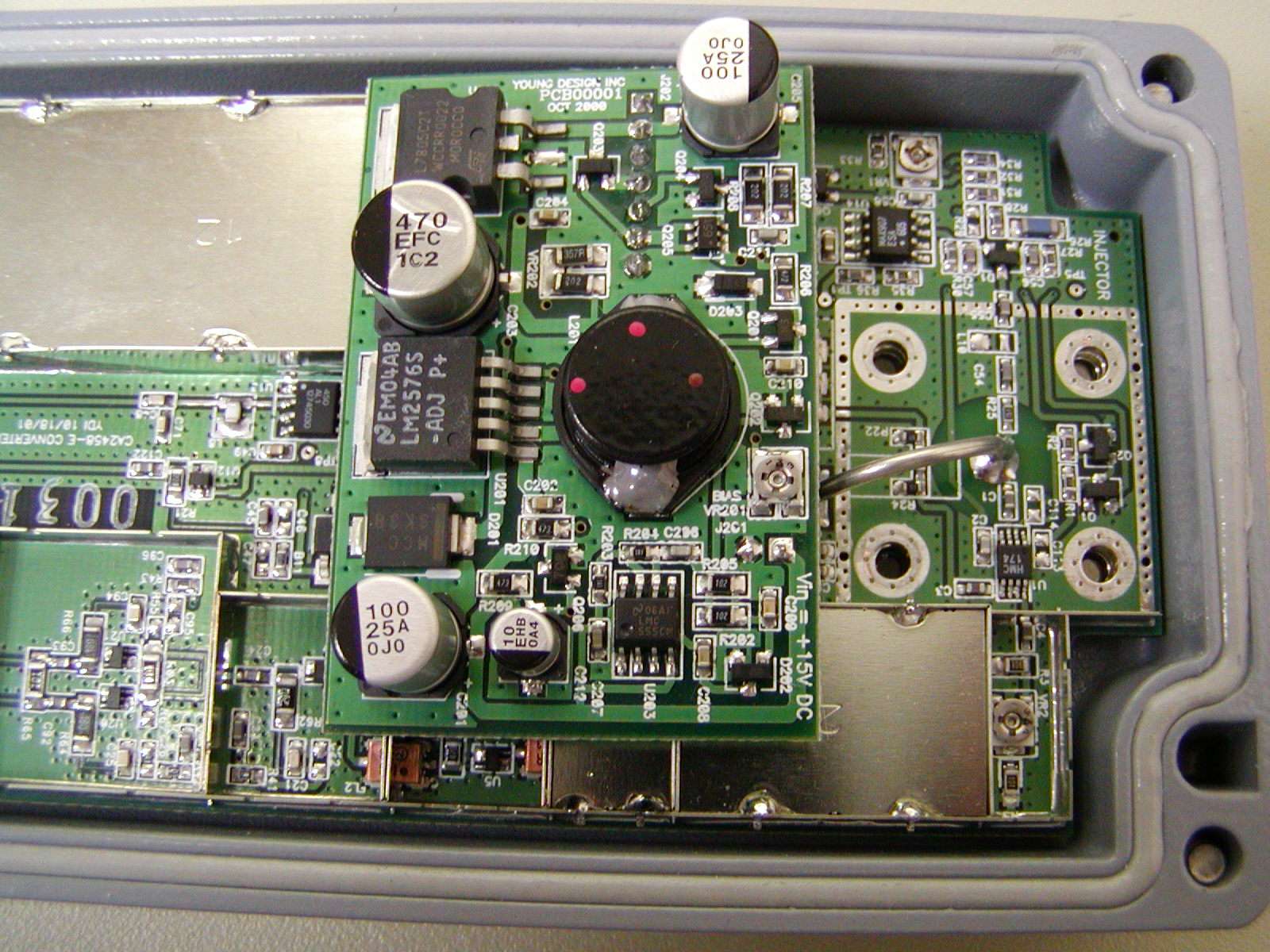
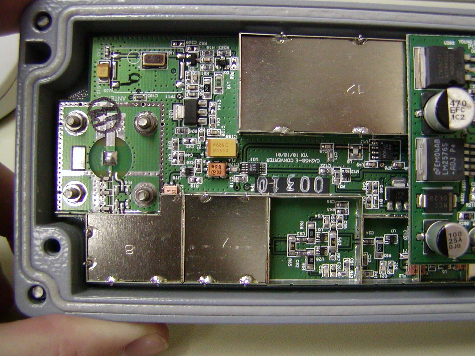
- YDI 2400-to-5800 converter - Pic 1
- YDI 2400-to-5800 converter - Pic 2
- YDI 2400-to-5800 converter - Pic 3
- YDI 2400-to-5800 converter - Pic 4
- YDI 2400-to-5800 converter - Pic 5
- YDI 2400-to-5800 converter - Pic 6
- YDI 2400-to-5800 converter - Pic 7
- YDI 2400-to-5800 converter - Pic 8
- Teletronics 1 Watt 2.4 GHz amplifier picture
Construction Notes
Start by reading the data sheet for the RF Micro Devices RF2126 1 watt 8-pin PSOP 2.4 GHz amplifier IC. If you are up to working with this device, call RFMD up at 336-664-1233 and order a few (around $7 each), or ask if they will send you some free engineering samples.
Next, read the data sheet for the Intersil HFA3424 2.4 GHz - 2.5 GHz low noise amplifier. It's also a 8-pin PSOP device. You can order these for around $8 each from Arrow Electronics or Allied Electronics.
Next, read the data sheet for the Intersil RF1K49093 8-pin PSOP power MOSFET. You can order these for around $2 each from Newark Electronics or Allied Electronics.
You'll want to pick up some quality 1/32 inch, double-sided, one ounce oz copper clad FR-4 circuit board. The Injectorall circuit board from Digi-Key is perfect. Its part number is PC44-ND for 3 x 4.5 inches and costs $3.23. Teflon circuit board has better characteristics at microwave frequencies so use that instead if you can find it. Down East Microwave and Rogers sell Teflon board. Note that you will need to change the widths of all the 50 ohm striplines in the schematic due to the lower dielectric constant of Teflon board material.
Now, make the circuit board for the amplifier. You'll have to do this by hand until someone makes me a PCB pattern. Heh. You can use those rub on thingys from Radio Shack (#276-1490) to layout the pattern. The 1 mm wide traces are almost perfect for 50 ohm striplines on 4.34 er, 1/32 inch FR-4 board material (actual width required is 1.4 mm) and the 2 mm traces are perfect 50 ohm for striplines on 2.55 er, 1/32" Teflon board material. Leave large pads for the components that require grounding, and try to remove all the copper around the paths where actual RF energy will flow. Consult the various microwave design books from the ARRL for more information on designing microwave circuits.
Here is a cool strip line calculator CGI to help in the design and analysis of strip line circuits.
Here are some links to help with the fabrication of your own printed circuit board:
- Making Excellent Printed Circuit Boards
- Tips from Mark Weiss
- Making PCBs at home
- PCB Designers Den by George Patrick
- Printed Circuit Prototyping
After your circuit board is etched, you should drill and solder all the ground vias. Those are what connects the top copper plane to the bottom plane on two sided copper clad boards. Do this by drilling small holes where proper grounding is required, then solder a piece of wire in the holes to connect the top and bottom planes. Cut off any excess length of wire flush to the copper plane. You can then start to solder in all the discrete components. Start with the small surface mount capacitors, resistors, and inductors, then move to the larger components. The very last thing to solder in will be the ICs. This is done to protect the ICs from any extended handling. Note that this is all easier said than done :)
It's also possible to make a receive only pre-amplifier by just replacing the power amplifier section with a 50 ohm stripline, or you can make a power amplifier only by replacing the receive section with a 50 ohm stripline.
It is possible to replace the RF2126 with a lower power or easier to obtain amplifier module. Examples are the WJ Communications AH102 which is good for about 250 mW of RF power (AH102 application note) or maybe even a Sirenza Microdevices SGA-6586 (100 mW). Be sure to watch the input RF powers on both devices.
Other replacement options for 2.4 GHz power amplifier MMICs are: M/A-Com MA02303GJ, Pacific Monoliths PM210x series, Raytheon PA2450, and various 2 GHz PCS phone MMICs.
Datasheets & Notes
- Intersil HFA3925 This is where I got the TX/RX switching idea from.
- PRISM1KIT-EVAL DSSS evaluation kit parts list Lists the actual manufacture part numbers in PRISM systems.
- NEC UPG152TA L-band SPDT GaAs MMIC switch Low power switch that is easy to obtain.
- Hittite HMC154S8 SPDT GaAs MMIC switch High power switch that is easy to obtain.
- Analog Devices AD8314 RF detector Used to detect incoming RF
- MMST2222A NPN transistor datasheet
- Application of PIN diodes From HP
- Fast switching PIN diodes From HP
- Applications for the HSMP-3890 surface mount switching PIN diode From HP
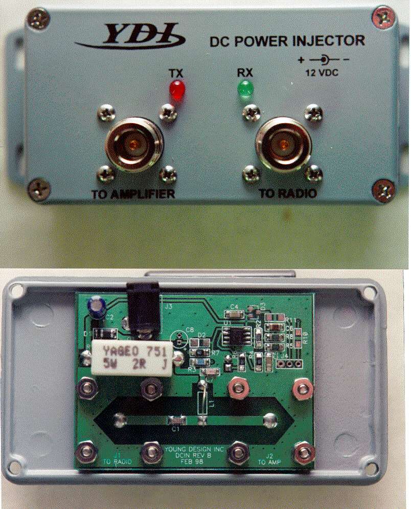
Insertion, DC Power Input & Control
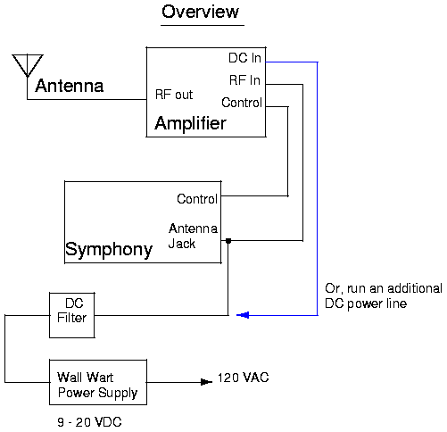
Stick the entire amplifier board inside a well designed waterproof case (Hammond boxes are perfect) and mount it right next to your antenna installation or on the antenna mast. You should run LMR-400 coax for the RF input feed line. The DC power for the amplifier is also inserted in this line, so you'll have to modify your Symphony to allow that. Run RG-6 quad-shield coax (Radio Shack #278-1317) for the amplifier's control line. Run this along side the RF input feed line and try to keep this line as short as possible. You can use normal F connectors on the control line if you desire.
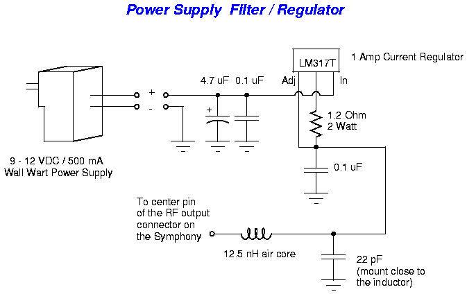
- Wall wart power supply filter
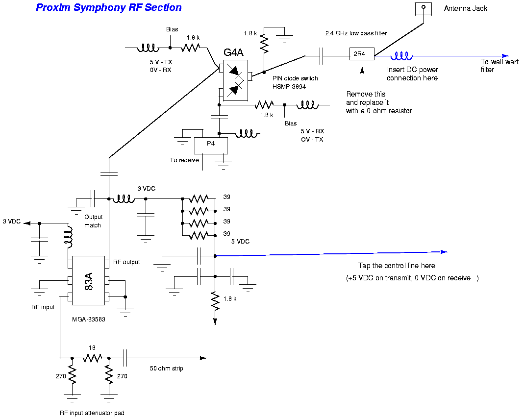
- DC power insertion on the Symphony
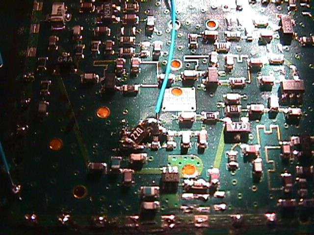
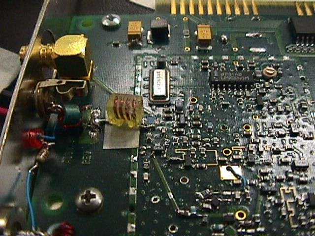
- Tap point for the amplifier control line inside the Symphony (blue wire)
The 22 ohm resistor is for the higher power modification and is not needed. Refer to the above diagram for more details.
- Amplifier's DC power insertion point inside the Symphony
It's also possible to provide the amplifier's DC power through an additional power line. You can do this if you don't want to modify your Symphony for DC power insertion on the RF output. Run the power in another run of RG-6 quad-shield, just like the control line.
- Overview of the power / control lines for the amplifier
Operation Notes
This bi-directional amplifier uses an external control line to switch between transmit and receive modes. This eliminates the complexity of a homebrew RF sense circuit. The components and design are such that anyone with some experience in microwave circuit construction should be able to build this amplifier. You can then mount this amplifier directly at the antenna or, for a much easier setup, just a few feet away from the Symphony card.
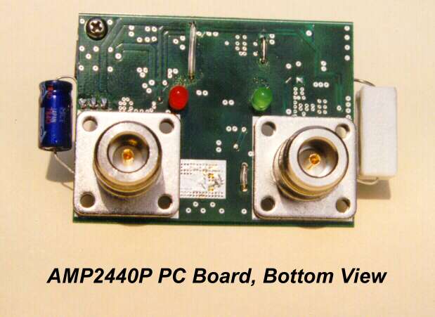
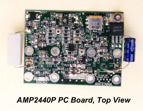
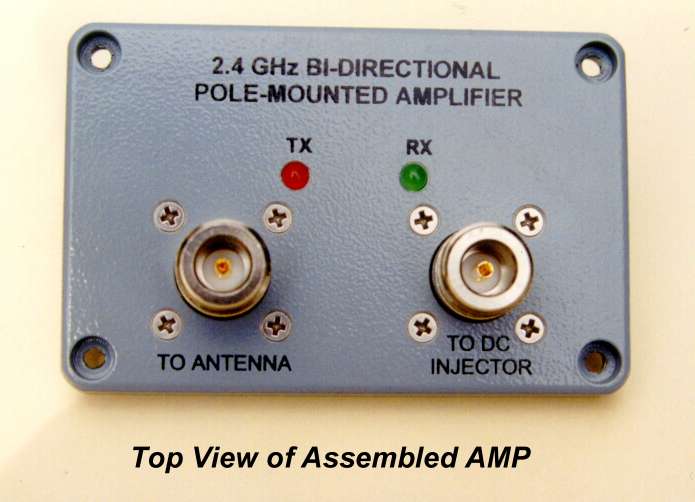
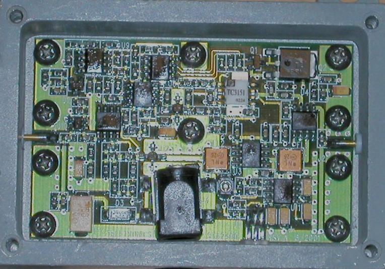
Pictures
View some of the construction pictures. Note that most of these cover prototype and experimental amplifiers.
Cautions & Notes
- You will need to completely shield the amplifier circuit when it's finished. Scrap copper clad PC board is perfect for this.
- Don't remove the control line while the Symphony is in operation or you'll end up transmitting into your receive pre-amp.
- Don't take candy from strangers.
[Code of Federal Regulations]
[Title 47, Volume 1, Parts 0 to 19]
[Revised as of October 1, 2000]
[CITE: 47CFR15.23]


                       TITLE 47--TELECOMMUNICATION

              CHAPTER I--FEDERAL COMMUNICATIONS COMMISSION

PART 15--RADIO FREQUENCY DEVICES--Table of Contents

                           Subpart A--General

Sec. 15.23  Home-built devices.

    (a) Equipment authorization is not required for devices that are not
marketed, are not constructed from a kit, and are built in quantities of
five or less for personal use.
    (b) It is recognized that the individual builder of home-built
equipment may not possess the means to perform the measurements for
determining compliance with the regulations. In this case, the builder
is expected to employ good engineering practices to meet the specified
technical standards to the greatest extent practicable. The provisions
of Sec. 15.5 apply to this equipment.
ANSI RF radiation dosage meter.
Return to the Low Cost Wireless Network How-To