Wideband PreAmp's for HF/VHF/UHF
![]()
Wideband
PreAmp's for HF/VHF/UHF
RE-HFA1MAR6 Wideband VHF/UHF/SHF monolithic PreAmp based on MARx-series
The
MAR6 (MSA-0686,0685,0885) is a high performance silicon bipolar
Monolithic Microwave Integrated Circuit (MMIC) housed in a low
cost, surface mount plastic package.
This MMIC is designed for use as a general purpose 50 W gain
block. Applications include narrow and broad band IF and RF
amplifiers in commercial and industrial applications.
The MSA-series is fabricated using HP’s 10 GHz fT, silicon
bipolar MMIC process which uses nitride self-alignment, ion
implantation, and gold metallization to achieve excellent
performance, uniformity and reliability. The use of an external
bias resistor for temperature and current stability also allows
bias flexibility. It is a Cascadable Silicon Bipolar MMIC
Amplifier.
Also usuable is the PGA103 :
PGA-103+ (RoHS compliant) is an advanced wideband amplifier
fabricated using E-PHEMT technology and offers extremely high
dynamic range over a broad frequency range and with low noise
figure. In addition, the PGA-103+ has good input and output
return loss over a broad frequency range without the need for
external matching components and has demonstrated excellent
reliability. Lead finish is SnAgNi. It has repeatable performance
from lot to lot and is enclosed in a SOT-89 package for very good
thermal performance.
MAR 6 and MAR 8 Features
(MSA-0685 & MSA-0885)
•
Frequency range from DC to 2GHz
• high gain, 22.5 dB (31.5dB MAR8) at 100 MHz, reduces
component count
• high power output, +12.5 dBm typ.
• low noise
• improved stability
• protection against power supply transients
• exact footprint substitute** MAR-8 and MSA-0885
..Compatible and even better is the PGA103
(works from 500kHz...4GHz, low noise)
• 3.2...4.2 volt @ pin 3
•
..
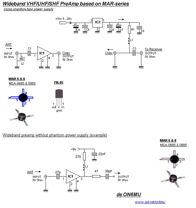
Schematic with external power supply

Components:
40Mc...2GHz
IC1 = MAR-6 or MAR-8 or MSA-0685 and MSA-0885 respectively,
PGA103
IC2 = 78L05
C1 = 56pF
C2 & C3 = 100pF
R1 Bias* = 120 (rev1.3)
C4 & C7 = 4.7uF/25v
C5 & C6 = 100nF
C8 = 560pF
L1 = 3 a 4 turns of 0.2 Cu wire through a ferite bead
L2 = 2,7uH or 4 turns of 0.2 Cu wire through a ferite bead
(optional, static blead)
D1 & D2 = 1N4148
1Mc...1GHz
C1 = 1000pF
C2 & C3 = 2200pF
L1 = 100uH
L2 = 47uH (optional, static blead)
PreAmp features:
• High
gain, 22.5 dB (31.5dB MAR8) at 100 MHz, 20dB @ 1GHz
• Can be used for TV and ATV reception too.
• Frequency range from +/- 30Mc to 2GHz (1Mc to 2GHz see
above components list)
• Voltage indepentend (8...20volts)
• Low current drain
• Static drainage (L2)
• Output protection (D1 D2 inverted diodes) for accidental
TX
• 50 Ohms input and output impedance
• Voltage indepentend (8...20volts)
• Dynamic range 14.5 dBm - 20dBm MAR 8
• VSWR in 1.5 out 1.8
• Noise < 3dB
Tips:
The best place to put a pre-amplifier is with out a
doubt as closest to the antenna as possible. If possible,
directly mounted at the feeder (dipole) and using phantom-type
powering of the amplifier. The RF/DC splitter comes inside the
shack just before your receiver.
Keep the connections as short as possible @ RF IN and RF OUT and keep them in 50 Ohms impedance starting at the leads from the IC. Mount it in a shielded casing.
With use with an transceiver: This preamp is protected to a certain degree for accidental TX (+/- 5watt) at the output, but no guarentee is given that your MAR-6 will survive. So make the needed precautions to prevent this from occuring when used in a TX type situation (like between your antenna and transceiver). Use a RF-sensing circuit instead.
When using it only with a receiver: you can leave out the parallel inverted diodes and C3.
L2 can be left out if your antenna has already some type of static bleeder build in (or DC shortened, like a folded dipole etc...). If you don't know for sure, just take your Ohm-meter and measure between the centre and the braid of the coax which should read something like < 1k or so. Inverted parallel diodes are also used to bleed of static build up. Test this with your diode tester. Ever so now and then (mostly with older type of RX verticals) a neon bulb is used hence never can be measured. Just leave L2 as it is (can't do much harm in any case stated above anyway).
Schematic with phantom power supply using the coax as feedline

RE-HFA1Q
General purpose RF Wideband PreAmp based on BSX-20 transistor
Features:
•
Frequency range from 14 to 550MHz
• Can be used for 50mc, FM-broadcast, VHF, UHF, TV...
• Average gain 12dB @ 145Mc
• Noise +/- 1.1dB
• Can be battery fed (7...15v)
• Low current drain: 6mA
• Easy and cheap to build, but not perfect.
Schematic

Notes: keep the connections as
short as possible @ RF IN and RF OUT and keep them in +/- 50 Ohms
impedance starting at the leads. Mount it in a shielded casing.
Don't forget to check
these out:
.ON6MU
Homebrew projects
.Radioamateur related projects
.ON6MU
Ham mods
.Modifications of transceivers
73"