NEGLECTED OLD TUBE RADIO
(2019)
KLIK HIER VOOR DE NEDERLANDSE VERSIE

In this state was the neglected old tube radio for sale at a flea market for 10 euros

And this is how the neglected radio has been refreshed!
Old Tube Radio
It was at the flea market and I bought it! I immediately was thinking about my student time and Alex. Alex was crazy about radio tubes! He was always busy with TVs and radios with tubes! Alex learned me how to fix a tube radio with a screwdriver-voltage tester. If it burns brightly, the voltage is high, if it burns weakly, then the voltage is low. That is how you can measure screen grid and anode voltages with it. And if you touch a grid with the screwdriver-voltage tester, you should hear hum!
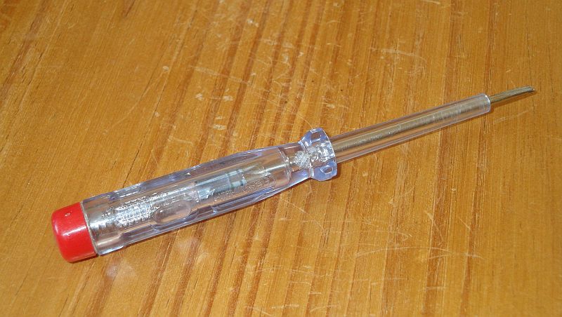
You can repair a tube radio with a screwdriver-voltage finder, no expensive voltmeter needed!
Alex kept talking about TVs with tubes, radios with beautiful wooden cabinets and bakelite cabinets and beautiful tuning capacitors. About antique red colored large tubes with top connections and modern smaller tubes. Great to see that beautiful technique. Everything was made with solder strips, parts through, under and above each other, no clear printed circuit boards! But I thought: Nice that there are printed circuit boards, transistors and ICs these days! Because that was more my thing.
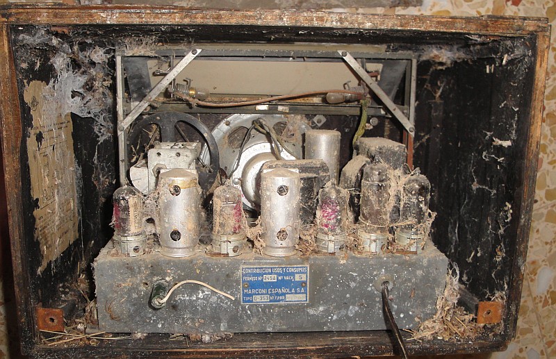
He was really dirty and badly neglected
What is it?
It is a Marconi, type Q353, built in Spain around 1950. So almost 70 years old! It still looked completely original, real Marconi tubes and no new parts. Except for the power supply capacitor, it was broken and bridged by a newer one that hung loosely under the chassis. After my student days I never saw a tube radio again. But on the internet you can find much information about those old radios and how to do such a repair or restoration. Alex had to do that without the internet, so for me it is much easier now.
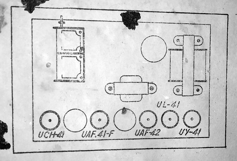
The tubes
UCH41 Mixing tube and oscillator
UAF41 Medium frequency amplifier (450 - 470 kHz)
UAF42 Low frequency amplifier and detection
UL41 Low frequency power tube
UY41 Rectifier tube
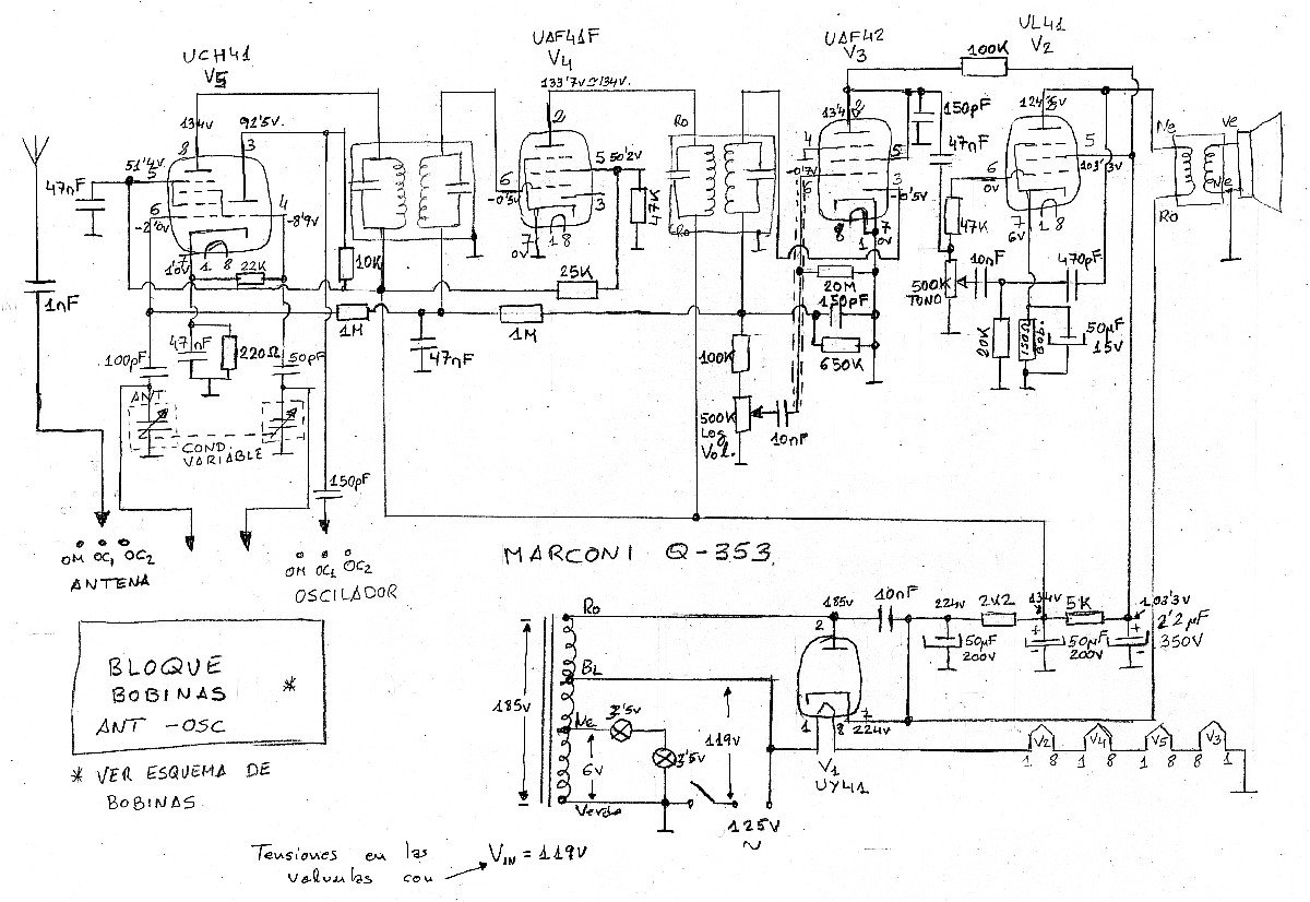
Antonio De Vega also has such a radio and made this diagram!
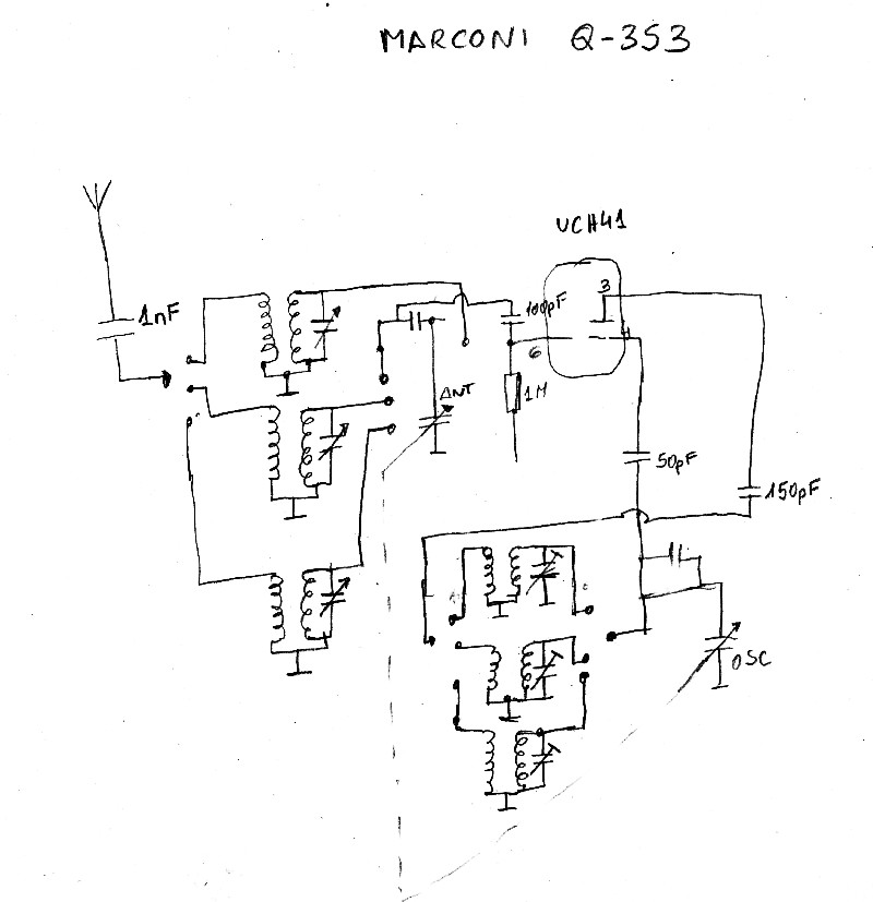
Part 2 of Antonio's diagram.
There are 5 tubes. Actually 4, one is the rectifier tube. Nowadays we use small semiconductor diodes for that. It has three bands. The medium wave and two short wave bands. No FM band. A real old radio as it should be! The tubes are U tubes, which are intended for use without a power transformer, the filaments are connected in series. The disadvantage is that the chassis is connected to the mains! But when you connect the mains plug in the right way into the socket, it is not the phase but the neutral that is connected to the chassis and there is no voltage on it. You can measure that with the screwdriver-voltage tester!
The tubes even had original labels!
Despite those U tubes, it still contains a transformer. It is not two separate windings, a primary and secondary windings, but one winding to increase the voltage. There is also a 5-volt tap for the scale lighting, two 2.5-volt lights in series. Fortunately, I discovered in time that it should be connected to 127 volts instead of the 230 volts we have today!
Except for the mains voltage there is only 1 connection, the antenna connection. No ground. The chassis is connected to the mains, so the mains is the opposite pole to the antenna. In the past a great solution, but nowadays with all those switching power supplies you can expect much of radio interference!
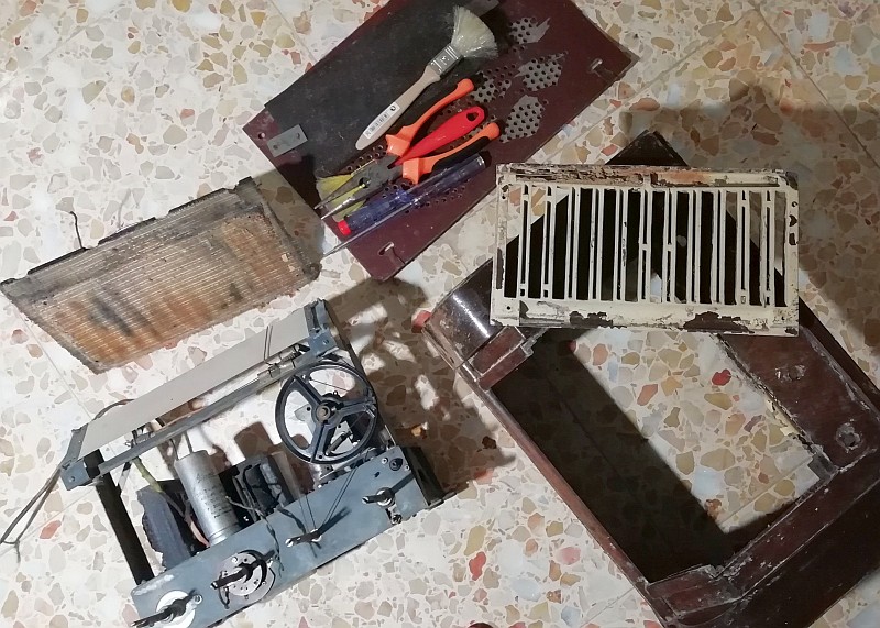
First take it apart and clean it completely with brushes, tweezers, soapy water and so on.
Removing the paint from the Bakelite front...
Cleaning and repairing the wooden cabinet
First take it apart and clean it completely with brushes, tweezers, soap, water and so on. On the guide rail of the tuning needle was a layer of dried grease. The bakelite knobs were very dirty, I cleaned then with soap and water. The speaker canvas had to be gently cleaned with soap and water and a cleaning spray. I removed the paint from the Bakelite front. Put it in water overnight with baking soda. I had no soda and took soap water. The paint was fairly easy to scratch off. The cabinet wood was delaminated and glued with wood glue. And, after a few evenings the radio looked much better! Just a small drop of oil on the potentiometer axes and the axis for the tuning.
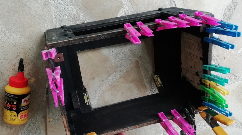
Glueing the laminated wooden case
Old parts need to be replaced.
In such an old receiver there are critical capacitors that you have to replace before you switch it on.
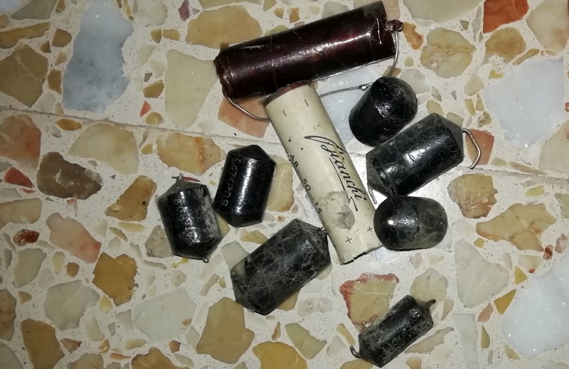
The critical capacitors in the radio
Fortunately, I had received a bag of capacitors, suitable for the high voltages in a tube radio. Cut the wires as close to the old capacitors as possible and solder the new capacitors to the old wires.
The black tar capacitors need to be replaced. When they are old, the insulation deteriorates and the leakage current increases. Maybe I could have left the ones placed over the cathode resistors, this is a very low-impedance and then a little leakage current doesn't matter. I replaced the 47 nF capacitors with available 0.1 uF polyester capacitors. A 10 nF capacitor in the tone control has been replaced by two 4700 pF ceramic capacitors connected in parallel.
The capacitor over the rectifier tube must be able to withstand high voltages. A 10 nF / 1 kV ceramic capacitor was available.
You should also replace capacitors marked "ERO". They are old paper capacitors that can explode! They weren't in this radio.
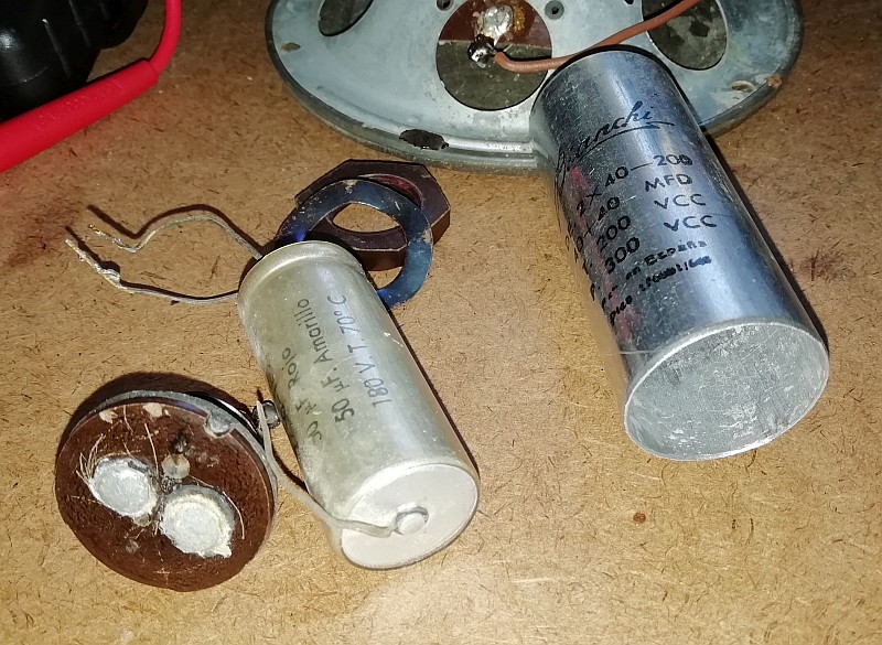
The electrolytic capacitors are old. They can get hot and explode due to high leakage current. So I replaced them by new ones. A 1 uF high voltage type was replaced by a new capacitor of 10 uF that was available here. The new capacitors are much smaller than the old ones!
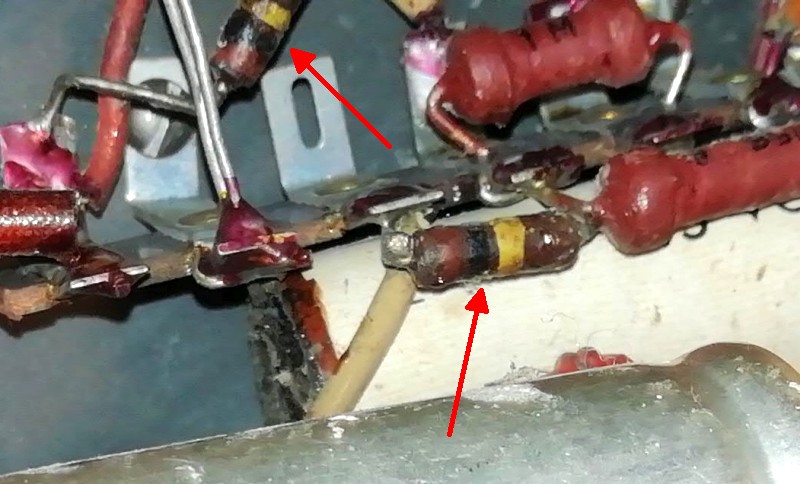
The critical resistances in the radio
And there are critical resistances that change in value or rustle and crack over time. See the picture above. They were still 115-120k ohms instead of 100k ohms, probably still acceptable. But I have renewed them. And there was wire whose insulation has hardened and broken. The wires to the speaker and to the power supply had to be renewed. And while replacing the components, some more old dead spiders were discovered!
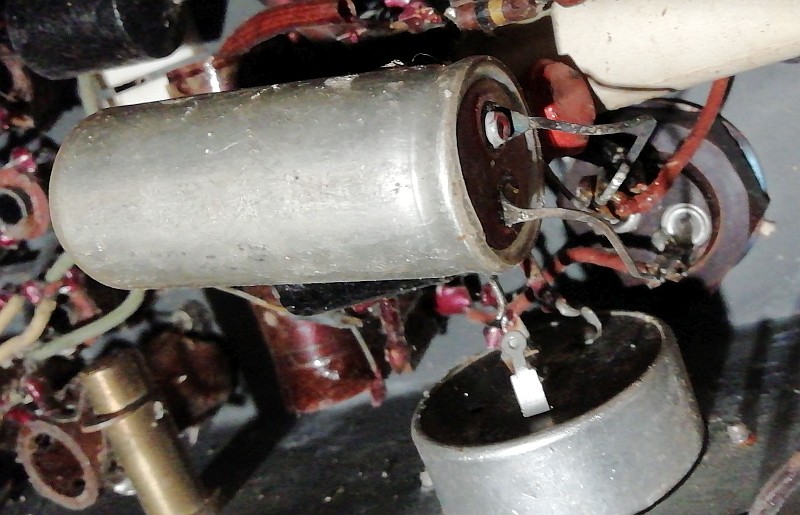
The replacement elco hanging in the chassis
The elco screwed onto the chassis was defective, it had no capacity left and had already been replaced by an elco that hung loosely between the parts under the chassis. It worked fine. But of course it is nicer to place it in the housing of the elco screwed onto the chassis. Not necessary, but a nice challenge!
The old defective capacitor is emptied and the replacement copy mounted
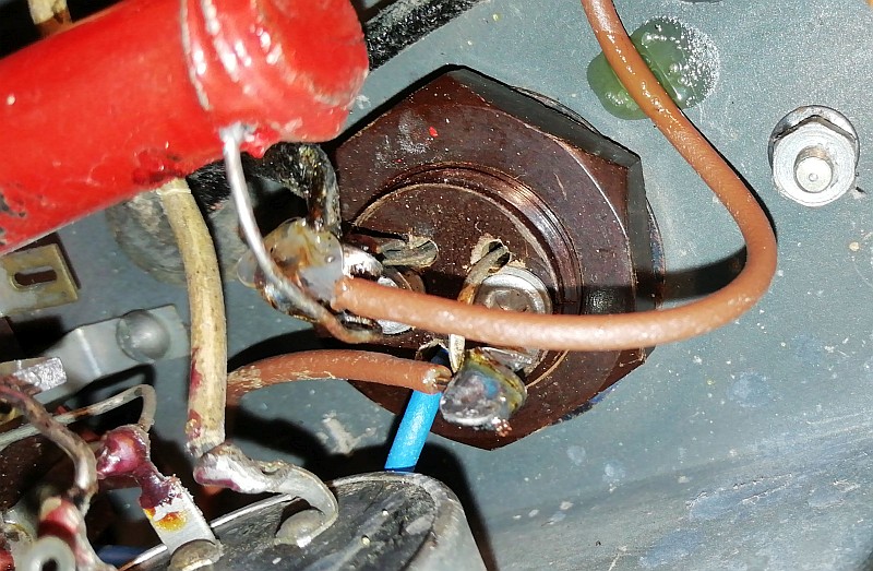
And this is what the result looks like. The blue wire is the new ground connection
And below are some pictures of how the radio looked in the past and now.
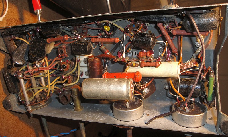
And this is what the bottom of the chassis looked like before the replacement of the parts
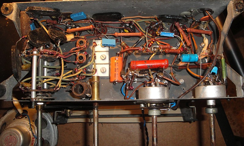
And this is how the bottom of the chassis looks like now
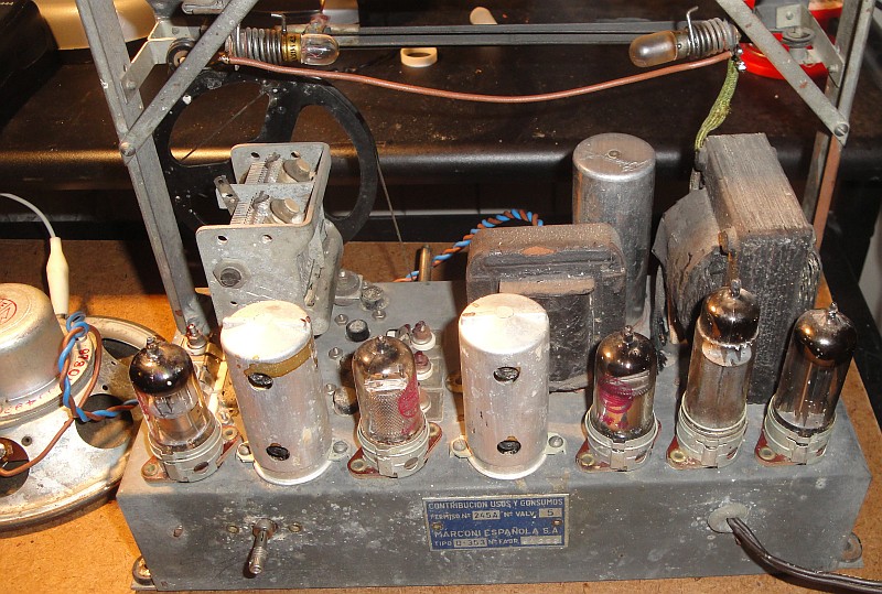
The top of the chassis, rear view
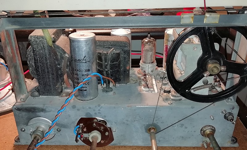
The top of the chassis, front view
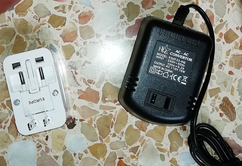
The transformer and travel adapter, I don't have a "USA" plug yet.
The 127 volt problem
And then there is the problem that the radio has to be powered with 127 volts. Internet provided the solution. Transformers are available to connect equipment from the USA (110 volts) to 230 volts in Europe. Ordered from an internet shop for about 20 euros. Unfortunately, this was not an isolation transformer, but one with 1 winding. One of the 110 volt outputs is therefore connected to the 230 volt mains! So for a safe situation we have to connect everything in such a way that the chassis of the radio is connected to the neutral of the mains. This is possible with the screwdriver-voltage tester. If it lights up brightly, the chassis is connected to the mains phase. Then turn the plug of the transformer. If it lights less brightly, it is connected to the center tap of the transformer and then you first need to turn the plug of the radio. If no light, then the chassis is connected to the neutral.
Another problem! The on / off switch of the radio is located in the connection between the chassis and the mains connection. When we turn off the radio, that connection is broken, the chassis floats. Then it is connected to the phase via the internal transformer and filaments of the tubes and the chassis is under tension! That's why I bridged the power switch with a wire. Then the chassis is always connected to the neutral of the mains.
De stroombegrenzer / softstart
Current limiter / soft start
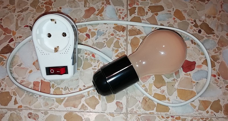
We have one more thing to do. When we switch on such an old radio after many years, we do that with a light bulb of 40-60 watts in series. When there is a short circuit in the device or any other fault, the current is limited by that light bulb. When everything seems right, we bridge the lamp with a switch.
I have left this circuit and now I also use it as a soft start. Then the tubes do not light up so brightly when you turn them on because the filaments heat up gradually.
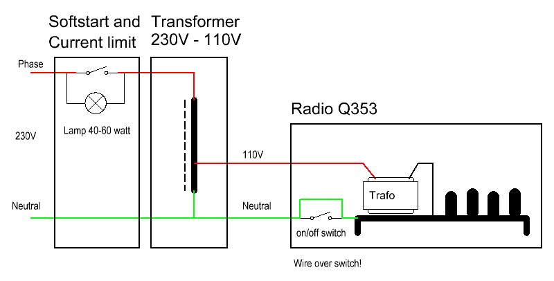
This is how the radio is connected to the mains
Shoes with insulating soles! We are going to work with high voltages and that must be done safely. Everything is connected as indicated above. Check again with the screwdriver-voltage tester if the neutral is really connected to the chassis of the radio and not the phase! Open the current limiter / soft start switch and connect the mains. The light bulb will burn dimly, a little brighter at first. Then the filaments of the tubes draw more current, their resistance is still low, they need to heat up for a while. And then we have to wait and see what happens. Is something going to smoke? Is something exploding?
A great receiver!
No! the radio just started playing !!! Just leave it like this for a few minutes and then switch the current limiter / soft start circuit lamp by switching the switch to "on". All tubes glowed as they should. No red anodes, no blue glowing gas! No creaking potentiometers! But they are of excellent quality, hermetically closed, so they are dustproof! The band switch creaked slightly, but after a few changes that was also resolved without cleaning it! Excellent sound and excellent reception on all bands! And all that after so many years! A great receiver! But some interference from all those switching power supplies that we have nowadays... Below a few 10 second audio recordings. And with the screwdriver-voltage tester I could indeed test all voltages. But times have changed, a good digital voltmeter costs almost nothing more, you can even buy in the supermarket and is much more accurate!
AUDIO RECORDING MEDIUM WAVE
AUDIO RECORDING SHORT WAVE
Index PA2OHH