PA0RDT MINI WHIP ANTENNA
(2022)
KLIK HIER VOOR DE NEDERLANDSE VERSIE
A small active antenna, I didn't expect too much from it!
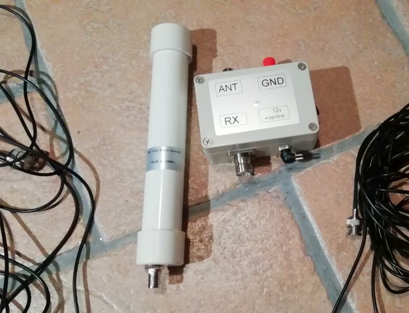
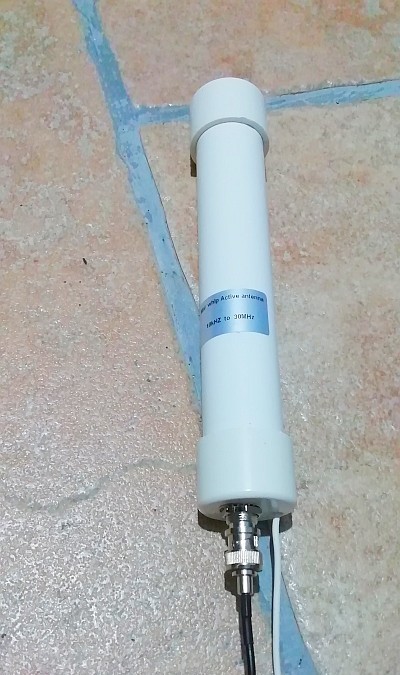
The PA0RDT mini whip antenna
A small active antenna as long as a foot, I wasn't expecting much from it at all! A small active antenna the size of my foot instead of a 5 meter long whip antenna, that's too nice to be true! But a small almost invisible whip antenna might still be quite useful for broadcast reception. And usable for all frequencies up to 30 MHz! I came up with a very simple way to test the sensitivity of such an active antenna. Without expensive measuring equipment, very suitable for a poor, soberly living radio amateur on bare feet. I wanted to try that test too. That little minwhip, I wanted to have it!
Such a small active whip antenna was ordered on the internet for about 50 euros, delivered at home. Making your own didn't seem like a good idea to me, it wasn't expensive and it came with two coax cables and a "power/splitter" so that the antenna can be fed with 12 volts via the coax.
I found an old satellite antenna wall bracket, a piece of PVC pipe of about 1.5 meters long, a box with hose clamps and I bought a long drill at the flea market. As the coax cable has to go somewhere through the thick wall. First we open the antenna, what would be in it??
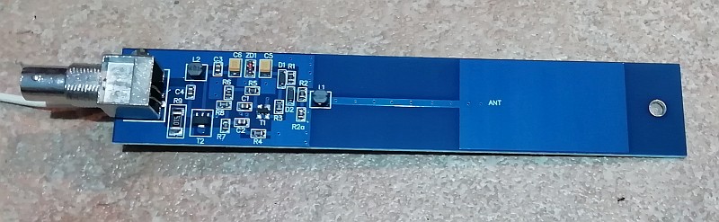
A nice printed circuit board with SMD's!
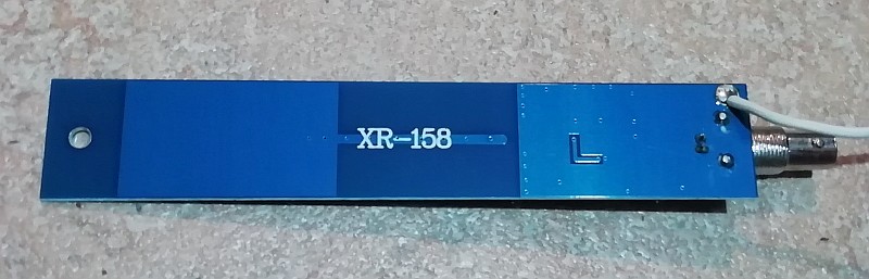
The rear of the PCB, type XR-158
Now that he has been taken apart, I also mounted a wire for grounding the antenna.
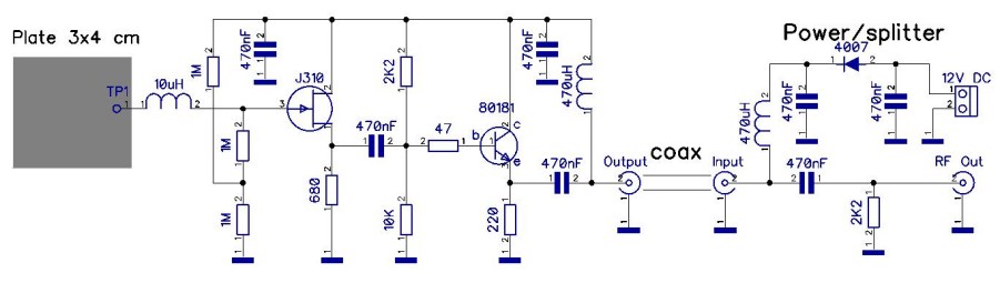
This is more or less how the diagram should look like
I made a hole in the bottom for the ground wire and the
draining of water if the antenna is not perfectly watertight...
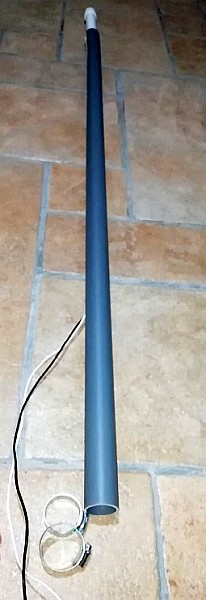
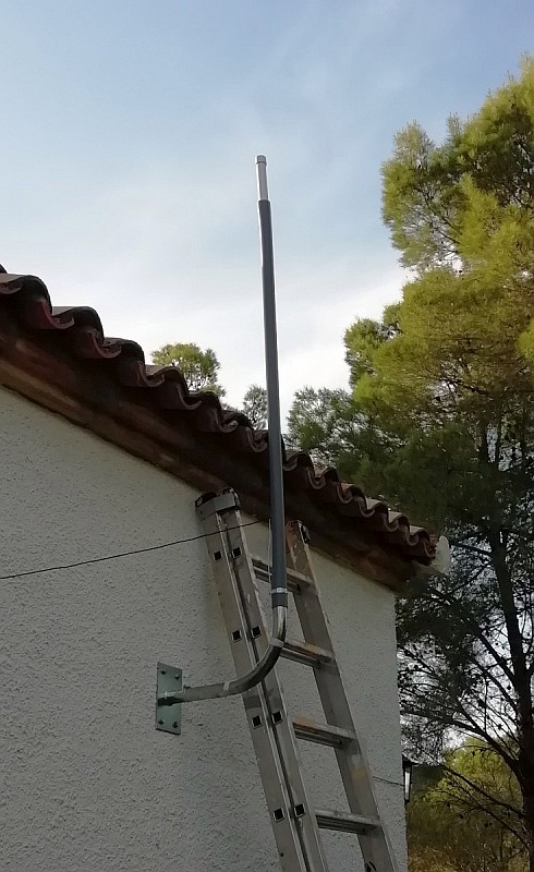
The antenna is mounted on top of a PVC pipe of approximately 1,5 meters length
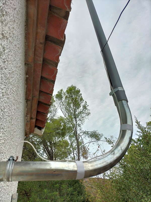
And the PVC pipe with antenna is mounted on the old
mounting bracket of a TV dish antenna.
The ground wire is connected to the metal mounting bracket.
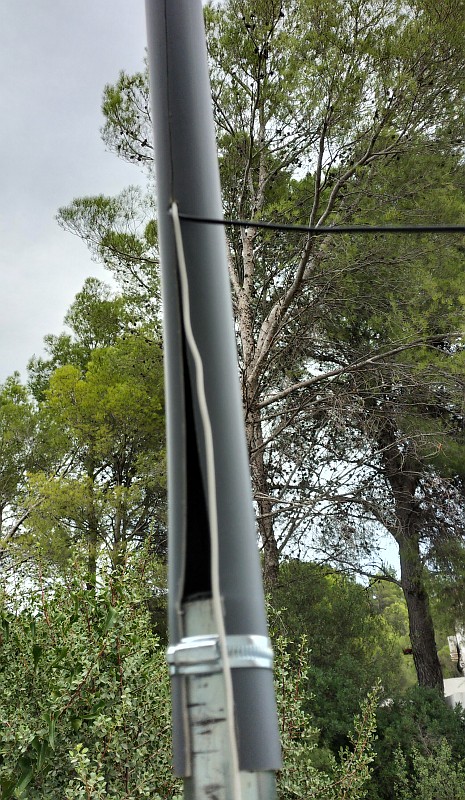
The PVC pipe is cut open lengthwise with a grinder
so that it clamps around the antenna and mounting bracket.
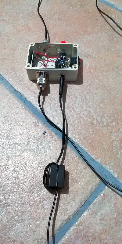
The power/splitter with a ferrite suppressor core in the supply line.
Power/splitter, radials and ferrites
Of course, you shouldn't take such a switched-mode power supply, it causes too much radio interference. There was still an old, analog unstabilized 12-volt power supply among the junk. An extra resistor and capacitor of 2000 uF was mounted in the power/splitter. The resistor to reduce the slightly overvoltage and the capacitor to reduce the ripple voltage. A ferrite core is mounted in the 12 volt supply line to suppress radio interference from the mains. Take 4 to 5 turns around the core, that is enough, 1 turn has practically no effect. And such a ferrite core is also mounted in every outgoing audio cable of a receiver.
The power/splitter is connected to two radials, one of approximately 2 meters in length and one of approximately 3 meters in length. This is how you make a good HF ground to reduce radio interference via the coax cables.
And also at the antenna you have to make an HF ground. I used the antenna bracket and didn't see much difference when adding extra radials. Those ugly radials have therefore been omitted.

An HF isolation transformer reduces the conductive radio interference from the receivers and computer equipment towards the antenna.
These are 2x8 bifiloair turns on an FT37-43 toroidal core. The windings are made from two twisted wires, then the losses are minimal.
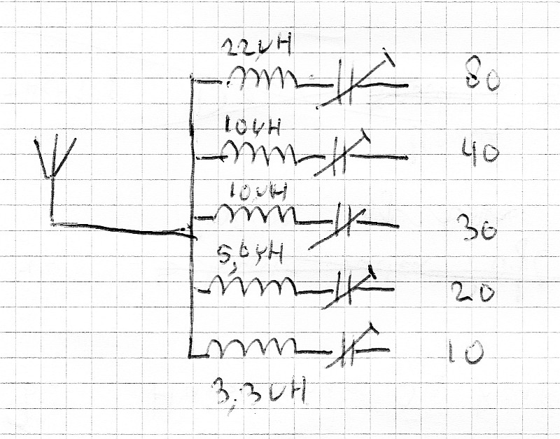
The receivers are connected via series resonant circuits. These have a low impedance on their own receiving frequency
and high impedance at other frequencies. So the receivers only load the antenna on their own frequency!
Connections with the QRSS receivers
An HF isolation transformer is inserted at the receivers side. An HF isolation transformer reduces the conductive radio interference from the receivers and computer equipment towards the antenna. These are 2x8 bifilair turns on an FT37-43 toroidal core. The windings are made from two twisted wires, then the losses are minimal.
The receivers are connected via series resonant circuits. These have a low impedance on their own receiving frequency and a high impedance on other frequencies. So the receivers only load the antenna on their own frequency!
If you still have some radio interference, you can experiment with radials at the output of the HF isolation transformer, so at the receivers.
The antenna is now ready for use. But how do you simply test the sensitivity of the antenna?
Test of the sensitivity at 40, 30, 20 and 10 meters, I made 1 picture of it.
During the first 30 seconds, the antenna is fully screened and you can see a low noise level.
After 30 seconds, the shielding is removed and you will see that the noise increases.
The ambient noise is therefore stronger than the antenna's own noise!
Sensitivity testing and... how does it perform?
How can you test the sensitivity of such an active antenna? That was not so difficult as you should expect. I wrapped the antenna completely in grounded aluminum foil so that it was totally shielded and did not receive anything. After that, the shielding is removed and the noise level should increase when the antenna is sensitive enough to receive the ambient noise or atmospheric noise!
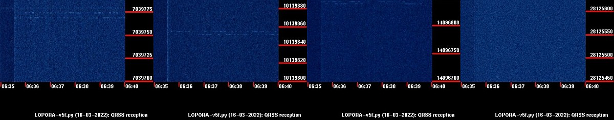
I have pasted the results of the four frequency bands next to each other so that you can see the results in one overview.
Test of the sensitivity at 40, 30, 20 and 10 meters, so I made 1 picture of it.
During the first 30 seconds after 6.35 am the antenna is shielded and you will see a low noise level. After 30 seconds, the shielding is removed and you will see that the noise increases slightly on all four bands. So on all bands, the ambient noise is stronger than the antenna's own noise, the sensitivity is excellent!
And the antenna works really well. Soon there were many QRSS signals visible on all bands. Below are some nice reception results of QRSS signals.
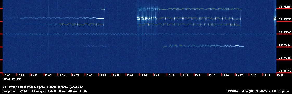
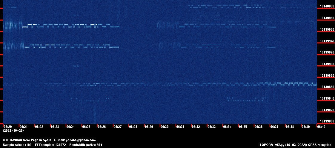
On 10 meter: G0MBA, G0PKT, M0GBZ, Pattern and PA2ST!
On 20 meter: G0FTD, VK4AAN (weak!), M0GBZ en TF3HZ!
Results 20 meters
Good reception from various QRSS stations. Even VK4AAN!
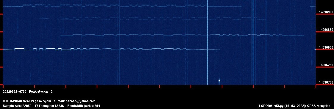
At 30 meters: KB5UEW!
Results 30 meters
Lots of QRSS signals! The 30 meter band is the busiest band with the most QRSS signals. This is the most suitable band to start with QRSS!
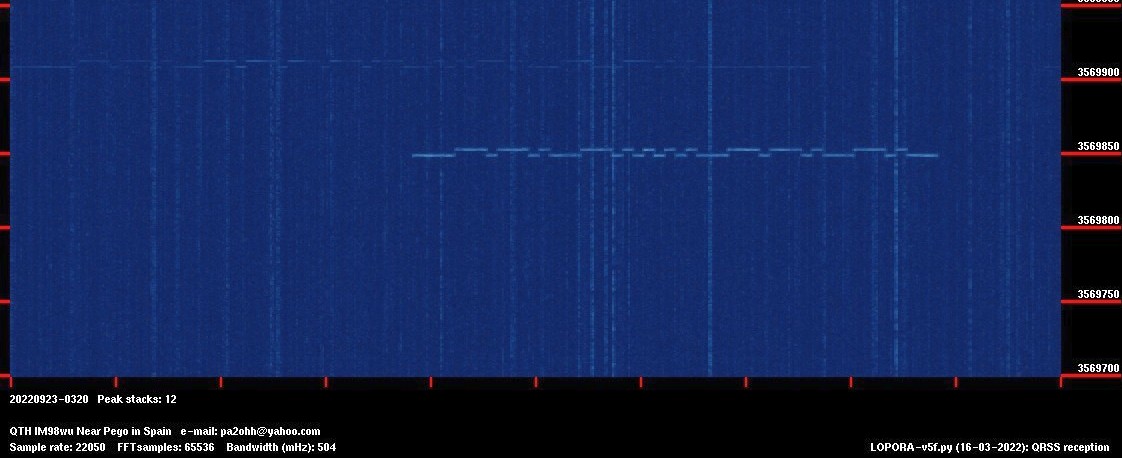
Seen at 40 meters: KG5RDY and K5CO!
Results 40 meters
Good reception from various QRSS stations. KG5RDY and K5CO with such a small mini whip antenna!
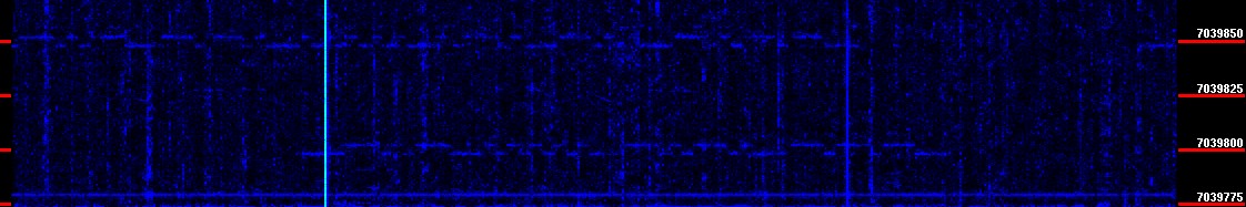
80 meters: G0FTD (weak!) and G6GN!
Results 80 meters
Good reception of some QRSS stations, often QRN.
A small active antenna, I expected very little from it...
But now it is my only antenna for receiving QRSS signals!
Amazingly good results!
The "poor man" sensitivity test proved that the antenna's sensitivity was fine. Soon many QRSS signals were received. The antenna worked great, much better than I expected. The supplied coax cables are not of a very high quality. No braided copper sheath and thin. But in practice, the antenna works well and the thin cable is very unobtrusive and easy to mount, so I'll leave it as it is.
And the bad weather did come. A lightning strike right next to the house, the mains fuse of the house had to be reset. But the antenna was not damaged. Good that I mounted the small whip antenna and not the 5 meter long whip antenna I wanted first!
A small, inconspicuous active whip antenna with the size of a foot. Only 1 antenna for all frequency bands and connected to all QRSS shortwave receivers! In an inconspicuous spot on the side of the house! Too good to be true, but it really is true! The 5 meter long, ugly whip antenna is now unused. But maybe I'll use it for a QRSS beacon for outside like Alex SA7CNG has, far from the house.
Index PA2OHH