VE7CNF - 630m Antenna Matching Measurements Using an Oscilloscope
Toby Haynes
October, 2016
VE7CNF - 630m Antenna Matching Measurements Using an Oscilloscope
Measuring Antenna Capacitance with a Temporary Variometer
Measuring Antenna Resistance at Resonance
Oscilloscope Probe Compensation
Reactance and Resonance Formulas
More Links:
PDF Version of Article
Simplified Version Web
and Simplified Version PDF
VE7CNF Amateur Radio Pages
Introduction
For operation on the 630m band I use an inverted-L antenna about 16 meters high. At 475 kHz the wavelength is very long and so the antenna is considered “electrically short” (much less than λ/4).
630m Band 472 –
479 kHz, center 475.5 kHz
Wavelength λ=630.9m, λ/2 = 315.5m, λ/4 = 157.7m
The inverted-L antenna uses a horizontal top-loading section that increases the current in the vertical radiating section. A loading inductor (variometer) is used at the base to resonate the antenna, and a transformer is used to match the antenna’s resistance to a 50-ohm transmission line.

This page describes how to use a signal generator and 2-channel oscilloscope to measure the antenna impedance, match the antenna, and tune it. By hooking up a simple resistive voltage divider at the base of the antenna, you can tune an MF/LF antenna for resonance and measure it’s resistance.

The main steps of the matching procedure are:
- Measure the antenna’s equivalent capacitance. To do this, a temporary variometer can be made to resonate the antenna.
- Make a permanent variometer with the proper inductance to resonate the antenna.
- Measure the equivalent resistance of the antenna system at resonance.
- Make a matching transformer to match the antenna system resistance to the transmission line.
- With the transformer and variometer connected, check that the tuning and impedance match are correct.
Measurements must be made at the base of the antenna, between the vertical wire and ground radials, where the matching network will be installed. The measurements won’t work through a length of coax.
To form the resistive divider, use a non-inductive resistor (carbon, metal film, metal oxide etc. in the 1/4W to 3W range). Don’t use a wire-wound resistor, even a “non-inductive” type.
When making AC measurements, it’s important to use x10 oscilloscope probes that have been properly compensated. See the “Oscilloscope Probe Compensation” section in the Appendix.
The method I describe works only at low frequencies. At higher frequencies the small capacitance of x10 scope probes will affect the measurements. I have used this method for the 2200, 630, and 160 meter bands.
To follow my descriptions you’ll need a basic understanding of inductance, capacitance, and reactance and be willing to do some arithmetic. See the Appendix if you like more equations.
References
There’s already a lot of great information on the web about low-frequency antennas and matching. Below are articles I found useful. Thanks to VE7SL for pointing me to some of these.
VK2DX “How-to-build-a-630m-antenna”
Inverted-L antenna and matching arrangement.
http://www.f6ciu.com/630m/630vk2/630vk.html
ON7YD “Antennas for 136 kHz” Detailed
information on LF antennas and matching.
http://www.strobbe.eu/on7yd/136ant/
VK1SV “Calculators Page” Efficiency
calculators for vertical and Marconi antennas.
http://people.physics.anu.edu.au/~dxt103/calculators/
N6LF “Some Thoughts on 630m
Verticals” parts 1 and 2
http://rudys.typepad.com/files/600m-verticals-part-1.pdf
http://rudys.typepad.com/files/600m-verticals-part-2.pdf
IN3OTD “Variometer Design” Calculators
for sliding and rotating variometers.
http://www.qsl.net/in3otd/variodes.html
Robert Weaver “Multi-Layer Coil
Inductance Calculator”
http://electronbunker.ca/InductanceCalcML.html
VE7SL “630m - Locked & Loaded”
A description of a large antenna with a matching network.
http://ve7sl.blogspot.ca/2014/09/630m-locked-loaded.html
VE7SL “The LF Station” Example 630m/2200m
station with useful links and references. See the “Scope Match.”
http://members.shaw.ca/ve7sl/2200mstn.html
VE7TIL “A Modern Amateur Longwave
Station”
http://www.nsarc.ca/hf/lw_stn.pdf
Antenna Equivalent Circuit
A low-frequency electrically short antenna can be represented by an equivalent series RC circuit. The capacitance Ca results from the electric field between the antenna wire and surrounding objects, the earth, and the ground radials. Wire inductance is not significant so the capacitance Ca dominates. The resistance Ra results from losses Rloss in the wire, surrounding objects, and earth. A small part of the total resistance is the “radiation resistance” Rrad, caused by the desired electromagnetic radiation. The actual capacitance and resistance are distributed across the antenna components, but the lumped series RC equivalent circuit is sufficient for antenna matching.

Some find the equivalent circuit counter-intuitive. Although there is no connection between the vertical wire and ground (GND), RF current still flows between the wire and ground due electric fields and the resulting capacitance. This is just as AC current flows through a capacitor, although there is no connection of conductors between the two ends of a capacitor.
Usually capacitance Ca will increase, loss resistance Rloss will decrease, and radiation resistance Rrad will increase as the antenna becomes higher, the top loading section becomes longer, and the ground system is improved.
Resistive Divider Formulas
To measure the antenna impedance and adjust the match, I use a resistive divider circuit. This is described in detail later, but here are the useful formulas:
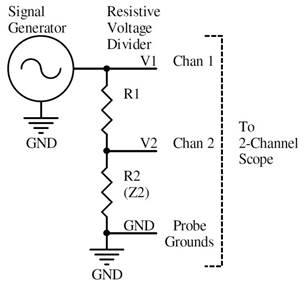
V1/V2 = (R1 + R2) / R2 V2/V1
= R2 / (R1 + R2)
R1 = R2 (V1/V2 – 1) R2 = R1 / (V1/V2 – 1)
V1 is the voltage measured between the top of the divider R1
and GND.
V2 is the voltage measured between the tap of the divider and GND, across R2.
V1 / V2 = 2, V2 / V1 = 1/2 when R1 = R2
V2 is in phase with V1 when R2 is resistive
If R2 contains some capacitance or inductance, then it’s actually an impedance (Z2) and there is a phase difference between voltages V1 and V2. All measurements described here are done when Z2 is tuned to resonance, so that it is equivalent to a resistor R2 and the voltage V1 and V2 are in phase.
Antenna Matching Measurements
See the reference VK2DX “How-to-build-a-630m-antenna” for the matching circuit. A transformer matches the antenna impedance to the transmission line, and a “variometer” inductor resonates the antenna.
For measurements below, use a signal generator set to the desired operating frequency f. It may be left indoors and connected to a transmission line (coax) that leads out to the antenna feedpoint. Set the signal generator voltage as high a possible while still producing a clean sine wave. A few volts peak-to-peak should work.
Measuring Antenna Capacitance with a Temporary Variometer
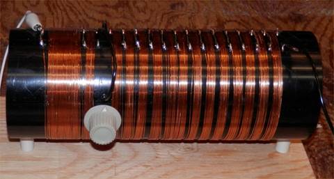
A temporary “test variometer” can be used to measure antenna capacitance. This variometer won’t have to handle any power so it can use thin wire. It doesn’t have to be neat, it just has to hold together long enough to complete the measurements.
First, guess at the antenna capacitance Ca, roughly 100 pF for a small antenna and 600 pF for a large one. Make a variometer inductor of the approximate inductance required to give resonance, in the 180 to 1100 uH range.
L = 1 / ( Ca (2 π f)2) Inductance
required for resonance, Henries
Ca is the antenna
capacitance, Farads
f is the operating
frequency, Hz
L = (d2 n2)
/ (18d + 40l) Inductance of an air-core coil, uH
d = Diameter inches
l = Length inches
n = Number of turns
It’s possible to wind thin scrap wire on a bucket, piece of pipe, or cardboard tube and add or remove turns to find resonance. A smaller diameter coil can be connected in series with a larger one, then slid in and out to adjust inductance to find resonance. Use the formulas above to estimate L and the number of turns needed on the coil forms you have available.

A “test variometer” wound on 3.5” O.D. ABS pipe. The internal rotating coil
is on 1.5” O.D. pipe.
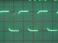
Connect the circuit below, outdoors at the base of the antenna. Set the signal generator to the desired operating frequency. Adjust the “test variometer” until the waveforms V1 and V2 are in phase. Voltage V2 should also be minimum at this setting. The variometer now has the proper inductance Lc for resonance at the operating frequency f.


Oscilloscope traces CH1 (V1) and CH2 (V2, lower amplitude trace)
3 Screens are: Lc too high, Lc correct (resonance), and Lc too low
Now the variometer inductance Lc must be measured. Disconnect the variometer and bring it indoors. Connect the circuit below with a known capacitor Ctest, say 220 pF.

Change the signal generator frequency to give minimum voltage V and note the resonant frequency ftest. Calculate the variometer inductance Lc. Calculate the antenna capacitance Ca at the operating frequency f.
Variometer Inductance Lc = 1 / (Ctest (2 π ftest)2)
Antenna Capacitance Ca = 1 / ( Lc (2 π f)2)
(Units are Henries, Farads, and Hz)
I have tried using a bridge circuit for measuring antenna capacitance. Pickup of AM radio signals and AC line noise made it impossible to find the null, so I gave up on that method.
Variometer Construction
Now that the antenna capacitance Ca is known, a permanent variometer can be designed with the proper inductance and thick enough wire and insulation to handle the planned operating power. See the references (http://www.qsl.net/in3otd/variodes.html and others).
L = 1 / ( Ca (2 π f)2) Variometer
inductance required for resonance, Henries
Ca is the antenna
capacitance, Farads
f is the operating
frequency, Hz
Variometers may have a rotating or sliding inner coil for adjustment. For transmitting, the wire gauge should be large enough to handle the required antenna current, say #18 to #10. Keep in mind that RF voltage on the end of the coil and the antenna wire may be several thousand volts, so use good insulating materials and leave clearances to avoid arcing.
Measuring Antenna Resistance at Resonance
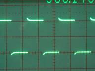
At the antenna feed point, connect the circuit below using the final variometer and a series resistor R1. Values shown in the diagram are what I measured for a 10 meter high inverted-L with 5 meter long top-load located near trees. Antenna resistance Ra may be from 20 to over 200 ohms on 630m depending on your setup.
Set the signal generator to the operating frequency f. Adjust the variometer for resonance such that V2 is in phase with V1. Voltage V2 should also be minimum at this setting.

Oscilloscope traces CH1 (V1) and CH2 (V2, lower amplitude trace)
3 Screens are: Lc too high, Lc correct (resonance), and Lc too low
Note the amplitude ratio V1/V2 and, with the known value of R1, calculate the total coil+antenna resistance R.
Total coil+antenna resistance R
= R1 / (V1/V2 – 1)
R = Rc
+ Ra
Best accuracy is obtained when R1 is approximately equal to R. Start with R1=100 ohms and then use an appropriate value for a final accurate measurement.
Build a Matching Transformer
Build a transformer to match the total resistance (R = Rc + Ra) to that of the 50-ohm transmission line. See the reference ON7YD “Antennas for 136 kHz” http://www.strobbe.eu/on7yd/136ant/ for good advice on this.

Transformer turns ratio N2 / N1 = √(R / 50) = √(
(Rc + Ra) / 50)
Transformer primary reactance XL1 = 2 π f L1 should be >500
ohms.
Transformer core should have low loss at f.
Use a large enough core and thick enough wire to handle the planned RF power. Ferrite cores have lower loss than powdered iron, but cost more and saturate easier.
A single-winding autotransformer is simpler to make and works just as well as a 2-winding transformer. A 2-winding transformer is needed if you want isolation, to keep RF current off the coax shield. Allowing RF current on the coax allows it to serve as another radial, but it will conduct RF into the shack and may increase receiver noise pickup from shack equipment.

Final Tuning and Test
Connect a test resistor R1, the transformer T1, and final variometer Lc to the antenna according to the following circuit. This test requires that R1 be near 50 ohms (47 ohms is accurate enough).

Set the signal generator to the operating frequency f. Adjust the variometer for resonance (V2 in phase with V1). If the match is correct then R2=R1 and so V2/V1 = 1/2. If necessary, adjust the transformer turns ratio so that V2/V1 = 1/2.
After everything checks out, short across R1 to remove it from the circuit. You can’t transmit very well if you leave it in!
Appendix
Oscilloscope Probe Compensation
The oscilloscope should have a bandwidth several times higher than the frequency to be tested, so that it does not shift the signal phase.
It’s important to use x10 scope probes to reduce circuit capacitive loading to about 15 pF. If you use x1 probes they will add 100 pF or more to the circuit being measured, and so results will be inaccurate.


A x10 Probe with Compensation Trimmer, and Oscilloscope Calibrator Test
Point
Always carefully adjust compensation on the x10 probes or they will not accurately measure AC waveform amplitude or phase. An uncompensated probe is either a high-pass or low-pass filter that will alter both amplitude and phase measurements.
Here are the compensation steps, to be done for each probe.
Switch the probe to x10 mode.
Clip the probe tip to the CAL or COMP test point on the front of the oscilloscope. For low-frequency compensation the probe ground lead can be unconnected, but ground it to the scope if you can.
Set the scope horizontal scale to the recommended setting for probe compensation, usually 1 ms/div.
Set the vertical scale and triggering to display the compensation waveform.
Adjust the probe compensation trimmer to give a square wave with a flat top and bottom.
For dual-trace oscilloscopes check that both channels are equally compensated by connecting both probes to the COMP test point at the same time. Verify that the two waveforms exactly overlap.
The following photos show the effects of the probe compensation trimmer. The center photos are the correct setting. The lower photos show how amplitude measurements are affected by incorrect compensation.


Probe compensation test point waveforms: low-pass, just right, and
high-pass.


Effect of probe compensation on AC amplitude measurements: low-pass,
just right, and high-pass.
It’s a mistake to use x1 probes or to skip probe compensation when making AC measurements.
Reactance and Resonance Formulas
Here are formulas for reactance, impedance, and resonance in RLC circuits:
XL = 2 π f L ZL
= j XL Inductive reactance and
impedance.
These
increase as frequency increases.
XC = 1 / (2 π f C) ZC
= -j XC Capacitive reactance and
impedance.
These
decrease as frequency increases.
Z = R + j XL -j XC
Total impedance of a
series RLC circuit.
At
resonance, XL and XC cancel and only R remains.
XL = XC ZL + ZC = 0 At resonance.
f = 1 / (2 π √(LC)) L = 1 / ( C (2 π f)2) C = 1 / ( L (2 π f)2) At resonance
f = Frequency Hz L =
Inductance in Henries
C = Capacitance in Farads X = Reactance in ohms
R = Resistance in ohms Z = Impedance in ohms
π = 3.1415927 j = √(-1)
(an “imaginary” number)
For an ideal inductor or capacitor the current i and voltage v are 90 degrees out of phase:
Inductor v = L di/dt di/dt
is the rate of change of current
Voltage leads current
by 90 degrees
Voltage is maximum when
current is changing most rapidly
Capacitor i = C dv/dt dv/dt
is the rate of change of voltage
Current leads voltage
by 90 degrees
Current is maximum when
voltage is changing most rapidly
A result of the voltage-to-current phase difference is that no power is dissipated by an ideal inductor or capacitor.
In AC circuit analysis the impedance of an inductor or capacitor is represented as an imaginary value (reactance X multiplied by j). By convention a capacitive impedance is considered negative. Inductive and capacitive impedances cancel each other in a circuit at resonance.
Measuring Resonance, L, and C
With a variable-frequency RF signal generator and oscilloscope, the resonant frequency of an LC circuit can be measured. If the inductor or capacitor has a known value then the equations above can be used to find the value of the unknown part.
The resonant frequency of a series LC circuit can be measured using a signal generator connected to the circuit through a resistor (value not critical, approx 47 ohms should work). An oscilloscope with a low-capacitance x10 probe measures the voltage across the series circuit. The AC voltage is minimum at resonance. Adjust the signal generator frequency f to give minimum voltage. If the LC circuit has low losses then the scope probe capacitance (10-20pF) can be ignored.

The resonant frequency of a parallel LC circuit can be measured using a signal generator coupled to the inductor with a couple of turns of wire. An oscilloscope with a low-capacitance x10 probe is connected to the circuit. The AC voltage is maximum at resonance. Adjust the signal generator frequency f to give maximum voltage. The scope probe capacitance (10-20pF) should be added to C for calculations.

If either L or C is known then the unknown component can be calculated.
L = 1 / ( C (2 π f)2) C = 1 / ( L (2 π f)2)
(Units are Henries, Farads, and Hz)
Inductance of Air Core Coils
The inductance of an air-core solenoid coil is approximately:
L = (d2 n2) / (18d + 40l)
L = Inductance in uH d = Diameter inches
l = Length inches n = Number of turns
Constraints are wire dia <0.1d and l=0.4d to 3d
Note that inductance increases as the square of the number of turns, and the square of the diameter.
When two coils are in close proximity their magnetic fields overlap, “coupling” occurs, and “mutual inductance” is created. The inductance of two coils in series can be greatly increased by bringing them together so they are magnetically coupled. Calculating the total inductance of coupled coils is complicated. See the references for online variometer and multilayer coil calculators, http://www.qsl.net/in3otd/variodes.html.
(c) Toby Haynes, VE7CNF. October, 2016