|
HAM Radio Projects |


|
Home |
|
My Station |
|
144MHz - DXCC, Grids, WAC Standings |
|
EME (Earth-Moon-Earth) My Initials |
|
PstRotator - Software for Antenna Rotators |
|
Photos |
|
HAM Radio Projects |
|
Some of my old electronic designs:
OrCAD 386+ files: *.sch - schematic diagram *.lib - components library *.bd1 - PCB design
1. ELECTRONIC CONTROL SYSTEM FOR AZ/EL ANTENNA ROTATOR
*** Moon Tracking System without PC ***
- Hardware based on a 80C552 microcontroller. - Specially designed for EME activities, with a moon tracking algorithm embedded. - Useful also for satellites tracking and the usual VHF or HF traffic. - Analog or incremental position readers jumper selected, AZ or EL independently. - 7 keys (UP, DOWN, LEFT, RIGHT, RESET/F1, MEM/F2, MODE/F3) keyboard. - one switch for MANUAL/AUTOMATIC modes switching. - 10 LED digits multiplexed display (5 digits to display the real AZ/EL antenna position, and other 5 for the computed position). - 4 mode indicator LEDs. Hardware specifications - 8k non-volatile memory (SRAM with internal battery and time keeper). - 32k program memory (EPROM). - watchdog. - optical-isolated serial RS232 port for communication with the PC or the GPS unit. - sound beeper. - 2 digital inputs (AZ/EL) for incremental position readers. - 2 10 bits ADC (AZ/EL) for analog position readers. - power MOSFETs driver bridge.
ANT.exe - configuration software
Hardware files OrCAD 386+ files: *.sch - schematic diagram *.lib - components library *.bd1 - PCB design
ANT.pdf - controller board ANT1.pdf - display and keyboard INOUT.pdf - input/output interface
Firmware files
ProView32 (Franklin) files:
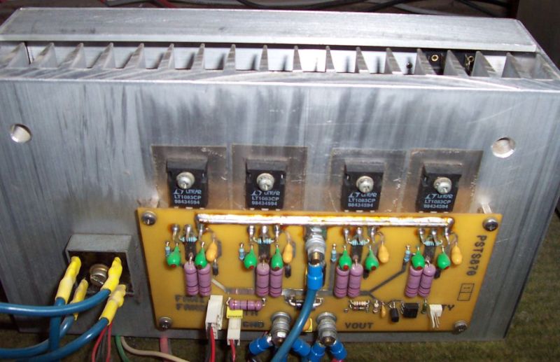
2. POWER SUPPLY 13.8V/30A for the HF transceivers using 4 x LT1083CP .
3. BEACON CONTROL MODULE with 2K EPROM memory
AQF.bin - EPROM example: (YO7AQF KN24KV 1W GP ANT BEACON -----)
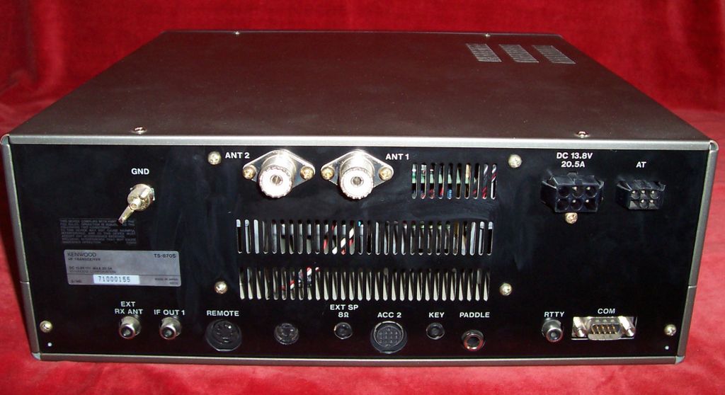
4. TS870 MODIFICATION FOR TRANSVERTER
Disclaimer : I take NO responsibility or liability of any kind for any possible equipment damage or any other inconvenience resulting from this modification. The user agrees to follow this modification on his own risk and expertise. This modification was tested only on my TS870 transceiver and it is performing as is described hereinafter.
Two small PCB’s. One of them is fitted with a connector for transverter. Appling 13.8V DC on VIN pin of this connector: - RX pin will be connected to the internal RX line of transceiver. - HF antenna will be disconnected from the internal RX line of transceiver. - TX pin will have a low level RF signal from the internal TX line. - PA input will be disconnected from the internal TX line. - a 50 ohm resistor will be added to the PA input. A new hole must be drilled on the rear panel of the TS870 transceiver ,between REMOTE connector and EXT SP jack. (see the picture). The relays are MEDER DIP05-1C90-51D type.
|