Example calculations zs6bkw antenna
This page details example antenna and feedline calculation for the ZS6BKW antenna using the program on the previous page
The ZS6BKW antenna comprises a dipole and matching section and is simply a re-dimensioned G5RV antenna.
The ZS6BKW antenna looks like this:
 For an antenna like this (14m+14m , 15metres up, the feedpoint impedances (EZNEC 2+) are approximately:
#
#ZS6BKW 14m+14m height=15m
28.5 310+590
24.95 125-500
21.2 3695-700
18.1 376+795
14.15 103-553
10.1 4676+2496
7.15 317+700
3.75 26-510
with 450 ohm line section 12.4 metres long
0.91 0.02(dB/100ft @1Mhz) 0.076 (dB/100ft @10Mhz) 0.27 (dB/100ft @100Mhz)
4 #ZS6BKW 14m+14m height=15m, feeder 12.4 m
28.5) Rin 113 Xin -122 (166 ohms) loss=0.12dB (SWR 50=5.2)
24.95) Rin 58 Xin -3 (58 ohms) loss=0.22dB (SWR 50=1.2)
21.2) Rin 1020 Xin 1596 (1894 ohms) loss=0.2dB (SWR 50=70.4)
18.1) Rin 83 Xin 5 (83 ohms) loss=0.11dB (SWR 50=1.7)
14.15) Rin 43 Xin 3 (43 ohms) loss=0.23dB (SWR 50=1.2)
10.1) Rin 396 Xin 1387 (1442 ohms) loss=0.22dB (SWR 50=105.1)
7.15) Rin 85 Xin -16 (86 ohms) loss=0.06dB (SWR 50=1.8)
3.75) Rin 14 Xin 103 (104 ohms) loss=0.54dB (SWR 50=19.6)
THEN with a length coaxial cable 75 ohm 5metres long
75ohm RG-59B Belden 8263, vf = 0.66, 0.6(dB/100ft@1Mhz) , 1.1(dB/100ft@10Mhz) , 3.4(dB/100ft @ 100Mhz)
5 ,75ohm feeder 5 m
28.5) Rin 24 Xin 12 (27 ohms) total loss=0.67dB (SWR 50=2.3)
24.95) Rin 72 Xin 18 (74 ohms) total loss=0.5dB (SWR 50=1.6)
21.2) Rin 82 Xin -340 (350 ohms) total loss=3.74dB (SWR 50=30.5)
18.1) Rin 79 Xin 8 (79 ohms) total loss=0.35dB (SWR 50=1.6)
14.15) Rin 68 Xin -39 (78 ohms) total loss=0.44dB (SWR 50=2.1)
10.1) Rin 3 Xin -1 (3 ohms) total loss=4.05dB (SWR 50=19.1)
7.15) Rin 61 Xin 0 (61 ohms) total loss=0.23dB (SWR 50=1.2)
3.75) Rin 997 Xin 358 (1060 ohms) total loss=0.9dB (SWR 50=22.5)
('total loss' is loss in 450ohm line + loss in 75 ohm line)
total feeders length 12.4 + 5=17.4 metres (antenna 15metres up)
instead of using 75ohm coaxial cable, 5m of 50ohm coaxial cable could be used instead
RG-58A Belden 8219, vf = 0.78, 0.4(dB/100ft@1Mhz), 1.3(dB/100ft@10Mhz) , 4.5(dB/100ft @ 100Mhz)
4 , feeder 5 m
28.5) Rin 17 Xin -33 (37 ohms) total loss=0.98dB (SWR 50=4.3)
24.95) Rin 55 Xin -6 (55 ohms) total loss=0.57dB (SWR 50=1.2)
21.2) Rin 34 Xin 169 (172 ohms) total loss=5.91dB (SWR 50=18.9)
18.1) Rin 47 Xin 22 (52 ohms) total loss=0.46dB (SWR 50=1.6)
14.15) Rin 54 Xin -9 (54 ohms) total loss=0.47dB (SWR 50=1.2)
10.1) Rin 2 Xin -12 (12 ohms) total loss=5.18dB (SWR 50=32.5)
7.15) Rin 34 Xin -15 (37 ohms) total loss=0.24dB (SWR 50=1.7)
3.75) Rin 407 Xin -465 (618 ohms) total loss=0.78dB (SWR 50=18.8)
('total loss' is loss in 450ohm line + loss in 50 ohm line)
total feeders length 12.4 + 5=17.4 metres (antenna 15metres up)
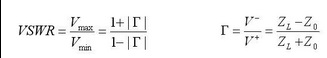
For 7.15Mhz, one might calculate the SWR as 50/sqrt(34*34 + 15*15) 0r 50/37 or 1.35, but this is incorrect.
The actual SWR is calculated with this formula):
For an antenna like this (14m+14m , 15metres up, the feedpoint impedances (EZNEC 2+) are approximately:
#
#ZS6BKW 14m+14m height=15m
28.5 310+590
24.95 125-500
21.2 3695-700
18.1 376+795
14.15 103-553
10.1 4676+2496
7.15 317+700
3.75 26-510
with 450 ohm line section 12.4 metres long
0.91 0.02(dB/100ft @1Mhz) 0.076 (dB/100ft @10Mhz) 0.27 (dB/100ft @100Mhz)
4 #ZS6BKW 14m+14m height=15m, feeder 12.4 m
28.5) Rin 113 Xin -122 (166 ohms) loss=0.12dB (SWR 50=5.2)
24.95) Rin 58 Xin -3 (58 ohms) loss=0.22dB (SWR 50=1.2)
21.2) Rin 1020 Xin 1596 (1894 ohms) loss=0.2dB (SWR 50=70.4)
18.1) Rin 83 Xin 5 (83 ohms) loss=0.11dB (SWR 50=1.7)
14.15) Rin 43 Xin 3 (43 ohms) loss=0.23dB (SWR 50=1.2)
10.1) Rin 396 Xin 1387 (1442 ohms) loss=0.22dB (SWR 50=105.1)
7.15) Rin 85 Xin -16 (86 ohms) loss=0.06dB (SWR 50=1.8)
3.75) Rin 14 Xin 103 (104 ohms) loss=0.54dB (SWR 50=19.6)
THEN with a length coaxial cable 75 ohm 5metres long
75ohm RG-59B Belden 8263, vf = 0.66, 0.6(dB/100ft@1Mhz) , 1.1(dB/100ft@10Mhz) , 3.4(dB/100ft @ 100Mhz)
5 ,75ohm feeder 5 m
28.5) Rin 24 Xin 12 (27 ohms) total loss=0.67dB (SWR 50=2.3)
24.95) Rin 72 Xin 18 (74 ohms) total loss=0.5dB (SWR 50=1.6)
21.2) Rin 82 Xin -340 (350 ohms) total loss=3.74dB (SWR 50=30.5)
18.1) Rin 79 Xin 8 (79 ohms) total loss=0.35dB (SWR 50=1.6)
14.15) Rin 68 Xin -39 (78 ohms) total loss=0.44dB (SWR 50=2.1)
10.1) Rin 3 Xin -1 (3 ohms) total loss=4.05dB (SWR 50=19.1)
7.15) Rin 61 Xin 0 (61 ohms) total loss=0.23dB (SWR 50=1.2)
3.75) Rin 997 Xin 358 (1060 ohms) total loss=0.9dB (SWR 50=22.5)
('total loss' is loss in 450ohm line + loss in 75 ohm line)
total feeders length 12.4 + 5=17.4 metres (antenna 15metres up)
instead of using 75ohm coaxial cable, 5m of 50ohm coaxial cable could be used instead
RG-58A Belden 8219, vf = 0.78, 0.4(dB/100ft@1Mhz), 1.3(dB/100ft@10Mhz) , 4.5(dB/100ft @ 100Mhz)
4 , feeder 5 m
28.5) Rin 17 Xin -33 (37 ohms) total loss=0.98dB (SWR 50=4.3)
24.95) Rin 55 Xin -6 (55 ohms) total loss=0.57dB (SWR 50=1.2)
21.2) Rin 34 Xin 169 (172 ohms) total loss=5.91dB (SWR 50=18.9)
18.1) Rin 47 Xin 22 (52 ohms) total loss=0.46dB (SWR 50=1.6)
14.15) Rin 54 Xin -9 (54 ohms) total loss=0.47dB (SWR 50=1.2)
10.1) Rin 2 Xin -12 (12 ohms) total loss=5.18dB (SWR 50=32.5)
7.15) Rin 34 Xin -15 (37 ohms) total loss=0.24dB (SWR 50=1.7)
3.75) Rin 407 Xin -465 (618 ohms) total loss=0.78dB (SWR 50=18.8)
('total loss' is loss in 450ohm line + loss in 50 ohm line)
total feeders length 12.4 + 5=17.4 metres (antenna 15metres up)
For 7.15Mhz, one might calculate the SWR as 50/sqrt(34*34 + 15*15) 0r 50/37 or 1.35, but this is incorrect.
The actual SWR is calculated with this formula):
 Notes on Matching section
The 12.4metre 450 section detailed above is 40.6 feet long (vf=0.91), and from W5DXP calculation at
https://web.archive.org/web/20210211105129/http://w5dxp.com/goodbad/goodbad.htm
Notes on Matching section
The 12.4metre 450 section detailed above is 40.6 feet long (vf=0.91), and from W5DXP calculation at
https://web.archive.org/web/20210211105129/http://w5dxp.com/goodbad/goodbad.htm
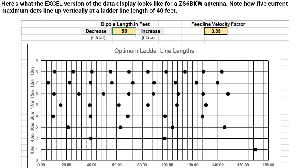 This graphic is shown when right clicking within SWR impedance box in LineZcalc2b (below).
Inverted U
The antenna can be bent into Inverted U shape, here 12metres up:
This graphic is shown when right clicking within SWR impedance box in LineZcalc2b (below).
Inverted U
The antenna can be bent into Inverted U shape, here 12metres up:
 the feedpoint impedances (EZNEC 2+) are approximately:
#
# ZS6BKW inverted U 7m+7m with 7.6m dangling each side height=12m
28.4 553+759
24.95 179-261
21.225 2018-1620
18.14 590+846
14.175 150-446
10.125 6583-2184
7.15 222+860
3.75 13-482
with the balanced line matching section 12.2metres long
450 ohm line
0.91 0.02(dB/100ft @1Mhz) 0.076 (dB/100ft @10Mhz) 0.27 (dB/100ft @100Mhz)
The feedpoint impedances are transformed to
3 # ZS6BKW inverted U 7m+7m with 7.6m dangling each side height=12m, feeder 12.2 m
28.4) Rin 119 Xin -113 (165 ohms) loss=0.11dB (SWR 50=4.7)
24.95) Rin 135 Xin 63 (149 ohms) loss=0.1dB (SWR 50=3.4)
21.225) Rin 1055 Xin 1468 (1808 ohms) loss=0.18dB (SWR 50=62)
18.14) Rin 101 Xin 11 (102 ohms) loss=0.09dB (SWR 50=2.1)
14.175) Rin 76 Xin 16 (78 ohms) loss=0.13dB (SWR 50=1.6)
10.125) Rin 386 Xin 1522 (1570 ohms) loss=0.26dB (SWR 50=127.8)
7.15) Rin 47 Xin -9 (48 ohms) loss=0.1dB (SWR 50=1.2)
3.75) Rin 8 Xin 109 (109 ohms) loss=0.97dB (SWR 50=35.9)
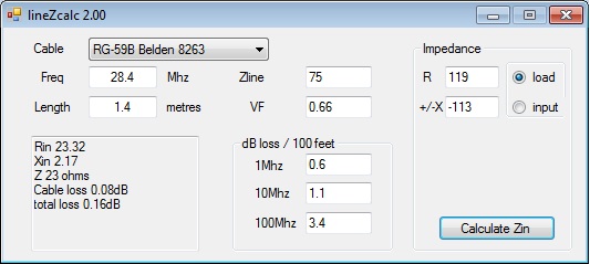
Then a length of 75 ohm cable
RG-59B Belden 8263, vf = 0.66 , 0.6(dB/100ft @1Mhz) 1.1(dB/100ft @10Mhz) 3.4(dB/100ft @100Mhz)
This could be 1.4 metres long
5 , feeder 1.4 m
28.4) Rin 23 Xin 2 (23 ohms) total loss=0.27dB (SWR 50=2.1)
24.95) Rin 51 Xin -47 (69 ohms) total loss=0.17dB (SWR 50=2.5)
21.225) Rin 4 Xin -58 (58 ohms) total loss=1dB (SWR 50=33.4)
18.14) Rin 79 Xin -25 (83 ohms) total loss=0.15dB (SWR 50=1.8)
14.175) Rin 94 Xin 3 (94 ohms) total loss=0.18dB (SWR 50=1.9)
10.125) Rin 7 Xin -175 (175 ohms) total loss=0.86dB (SWR 50=101.9)
7.15) Rin 47 Xin 6 (47 ohms) total loss=0.17dB (SWR 50=1.1)
3.75) Rin 15 Xin 161 (162 ohms) total loss=1.26dB (SWR 50=37)
total feeders length 12.2 + 1.4=13.6 metres (antenna 12metres up)
or if a longer feeder length required, 5.2 metres of 75 ohm cable:
5 , feeder 5.2 m
28.4) Rin 28 Xin 23 (36 ohms) total loss=0.65dB (SWR 50=2.3)
24.95) Rin 61 Xin -53 (81 ohms) total loss=0.44dB (SWR 50=2.6)
21.225) Rin 33 Xin -204 (207 ohms) total loss=3.47dB (SWR 50=27.3)
18.14) Rin 95 Xin 17 (96 ohms) total loss=0.35dB (SWR 50=2)
14.175) Rin 61 Xin 1 (61 ohms) total loss=0.34dB (SWR 50=1.2)
10.125) Rin 3 Xin 5 (6 ohms) total loss=4.82dB (SWR 50=19.8)
7.15) Rin 84 Xin 36 (92 ohms) total loss=0.32dB (SWR 50=2.1)
3.75) Rin 1531 Xin -777 (1717 ohms) total loss=1.56dB (SWR 50=38.5)
('total loss' is loss in 450ohm line + loss in 75 ohm line)
total feeders length 12.2 + 5.2=17.4 metres (antenna 12metres up)
1.4 metres of coax makes a difference:
the feedpoint impedances (EZNEC 2+) are approximately:
#
# ZS6BKW inverted U 7m+7m with 7.6m dangling each side height=12m
28.4 553+759
24.95 179-261
21.225 2018-1620
18.14 590+846
14.175 150-446
10.125 6583-2184
7.15 222+860
3.75 13-482
with the balanced line matching section 12.2metres long
450 ohm line
0.91 0.02(dB/100ft @1Mhz) 0.076 (dB/100ft @10Mhz) 0.27 (dB/100ft @100Mhz)
The feedpoint impedances are transformed to
3 # ZS6BKW inverted U 7m+7m with 7.6m dangling each side height=12m, feeder 12.2 m
28.4) Rin 119 Xin -113 (165 ohms) loss=0.11dB (SWR 50=4.7)
24.95) Rin 135 Xin 63 (149 ohms) loss=0.1dB (SWR 50=3.4)
21.225) Rin 1055 Xin 1468 (1808 ohms) loss=0.18dB (SWR 50=62)
18.14) Rin 101 Xin 11 (102 ohms) loss=0.09dB (SWR 50=2.1)
14.175) Rin 76 Xin 16 (78 ohms) loss=0.13dB (SWR 50=1.6)
10.125) Rin 386 Xin 1522 (1570 ohms) loss=0.26dB (SWR 50=127.8)
7.15) Rin 47 Xin -9 (48 ohms) loss=0.1dB (SWR 50=1.2)
3.75) Rin 8 Xin 109 (109 ohms) loss=0.97dB (SWR 50=35.9)
Then a length of 75 ohm cable
RG-59B Belden 8263, vf = 0.66 , 0.6(dB/100ft @1Mhz) 1.1(dB/100ft @10Mhz) 3.4(dB/100ft @100Mhz)
This could be 1.4 metres long
5 , feeder 1.4 m
28.4) Rin 23 Xin 2 (23 ohms) total loss=0.27dB (SWR 50=2.1)
24.95) Rin 51 Xin -47 (69 ohms) total loss=0.17dB (SWR 50=2.5)
21.225) Rin 4 Xin -58 (58 ohms) total loss=1dB (SWR 50=33.4)
18.14) Rin 79 Xin -25 (83 ohms) total loss=0.15dB (SWR 50=1.8)
14.175) Rin 94 Xin 3 (94 ohms) total loss=0.18dB (SWR 50=1.9)
10.125) Rin 7 Xin -175 (175 ohms) total loss=0.86dB (SWR 50=101.9)
7.15) Rin 47 Xin 6 (47 ohms) total loss=0.17dB (SWR 50=1.1)
3.75) Rin 15 Xin 161 (162 ohms) total loss=1.26dB (SWR 50=37)
total feeders length 12.2 + 1.4=13.6 metres (antenna 12metres up)
or if a longer feeder length required, 5.2 metres of 75 ohm cable:
5 , feeder 5.2 m
28.4) Rin 28 Xin 23 (36 ohms) total loss=0.65dB (SWR 50=2.3)
24.95) Rin 61 Xin -53 (81 ohms) total loss=0.44dB (SWR 50=2.6)
21.225) Rin 33 Xin -204 (207 ohms) total loss=3.47dB (SWR 50=27.3)
18.14) Rin 95 Xin 17 (96 ohms) total loss=0.35dB (SWR 50=2)
14.175) Rin 61 Xin 1 (61 ohms) total loss=0.34dB (SWR 50=1.2)
10.125) Rin 3 Xin 5 (6 ohms) total loss=4.82dB (SWR 50=19.8)
7.15) Rin 84 Xin 36 (92 ohms) total loss=0.32dB (SWR 50=2.1)
3.75) Rin 1531 Xin -777 (1717 ohms) total loss=1.56dB (SWR 50=38.5)
('total loss' is loss in 450ohm line + loss in 75 ohm line)
total feeders length 12.2 + 5.2=17.4 metres (antenna 12metres up)
1.4 metres of coax makes a difference:
 update for program to show SWR lineZcalc2b.zip 6C90741F
This 2b program replaces the previous one, so rename (or delete) the original lineZcalc2.exe and then
rename lineZcalc2b.exe to lineZcalc2.exe. This allow the program to work with the dotnet .config.exe setup.
[calculations ver 1.0]
Notes
The antenna feedpoint impedance (on the antenna wire) have been estimated with EZNEC. This uses an estimate of
ground conductivity that is much the same as an adjustment of impedance depending on the height of the antenna
above ground. One method to estimate the actual feedpoint impedance (on the antenna wire connections) is to use
a (low impedance unbalanced line) impedance meter at the radio end of the 75 ohm cable. Then with the program,
check the "input" radio button, enter the impedances seen at radio end of 75ohm cable and the program will
calculate the impedances at the junction of the 450 ohm and 75 ohm cables. Then again, using these calculated
numbers one can calculate the impedances at the antenna wire feedpoint. (The program has a cables data file
allowing specification of the actual cables used for the antenna). Notice that the 75 ohm line is not operated as
a flat line- the impedance at the radio end of the 75ohm line depends on the length of the 75ohm line.
For the inverted U arrangement, some small radiation from the balanced line occurs to distort the antenna pattern
and the balanced line can be led away from the antenna at some angle instead.
Mastering the (dipole) dip
update for program to show SWR lineZcalc2b.zip 6C90741F
This 2b program replaces the previous one, so rename (or delete) the original lineZcalc2.exe and then
rename lineZcalc2b.exe to lineZcalc2.exe. This allow the program to work with the dotnet .config.exe setup.
[calculations ver 1.0]
Notes
The antenna feedpoint impedance (on the antenna wire) have been estimated with EZNEC. This uses an estimate of
ground conductivity that is much the same as an adjustment of impedance depending on the height of the antenna
above ground. One method to estimate the actual feedpoint impedance (on the antenna wire connections) is to use
a (low impedance unbalanced line) impedance meter at the radio end of the 75 ohm cable. Then with the program,
check the "input" radio button, enter the impedances seen at radio end of 75ohm cable and the program will
calculate the impedances at the junction of the 450 ohm and 75 ohm cables. Then again, using these calculated
numbers one can calculate the impedances at the antenna wire feedpoint. (The program has a cables data file
allowing specification of the actual cables used for the antenna). Notice that the 75 ohm line is not operated as
a flat line- the impedance at the radio end of the 75ohm line depends on the length of the 75ohm line.
For the inverted U arrangement, some small radiation from the balanced line occurs to distort the antenna pattern
and the balanced line can be led away from the antenna at some angle instead.
Mastering the (dipole) dip
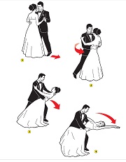 If the dipole type antenna is connected to coaxial cable (flat line), the antenna has to be resonant.
So the antenna flattop has to be pruned to length. This does not necessarily mean cutting bits off and
adding them back on. The ends of a dipole are at high voltage (high impedance) and are usually connected
directly to the support insulators to prevent antenna detuning. An improved method is to support the flattop
some distance in from the end of the antenna and leave the remainder of the flat top dangling at each end.
If uninsulated wire is used and the antenna is cut somewhat longer than anticipated, then pruning the antenna
is as simple as folding some short length of wire back up the dangly section and reconnecting it...
Or use a sliding adjustable connection; for the antennas shown above, this is much the same as adjusting the length
of the matching section.
If the dipole type antenna is connected to coaxial cable (flat line), the antenna has to be resonant.
So the antenna flattop has to be pruned to length. This does not necessarily mean cutting bits off and
adding them back on. The ends of a dipole are at high voltage (high impedance) and are usually connected
directly to the support insulators to prevent antenna detuning. An improved method is to support the flattop
some distance in from the end of the antenna and leave the remainder of the flat top dangling at each end.
If uninsulated wire is used and the antenna is cut somewhat longer than anticipated, then pruning the antenna
is as simple as folding some short length of wire back up the dangly section and reconnecting it...
Or use a sliding adjustable connection; for the antennas shown above, this is much the same as adjusting the length
of the matching section.